Description
The blue GHB-3M30-B and GHB-,
5M30-B and green GHB-3M30-G
LEDs are designed in
an industry standard T-1 3/4 and
T-1 packages with clear and non-
diffused optics.
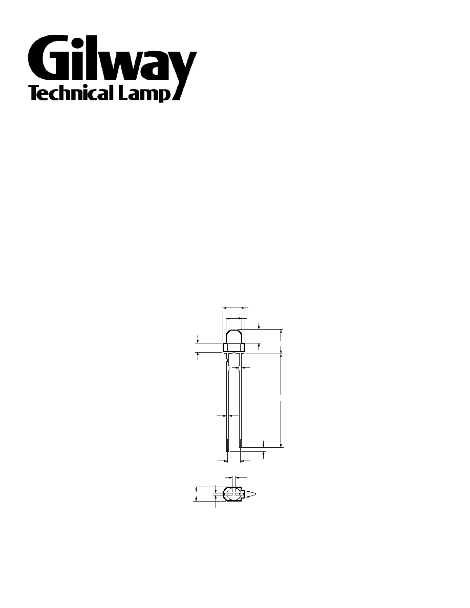
Package Dimensions
NOTES:
1. ALL DIMENSIONS ARE IN MILLIMETERS (INCHES).
2. EPOXY MENISCUS MAY EXTEND ABOUT 1 mm (0.040")
DOWN THE LEADS.
5.85 ± 0.50
23.0 MIN.
2.54 ± 0.30
4.40 ± 0.30
3.10 ± 0.20
3.50 ± 0.30
1.0 MIN.
2.00
3.40 ± 0.20
0.44
± 0.20
+ 0.10
0.40 – 0
C
MA
ATRHKO
SDE
+ 0.10
0.45 – 0.04
0.65 MAX.
55 Commerce Way
Woburn, MA 01801
(781) 935 - 4442
(781) 938 - 5867
www.gilway.com
GHB-3M30-B
GHB-3M30-G
GHB-5M30-B

Selection Guide
Package
Luminous Intensity Iv (mcd) @ 20 mA
Description
Color
Part Number
Min.
Max.
DC Current
[1]
Reverse Voltage (I
R
= 100m
Dip/Drag Solder Temperature
260 ∞C for 5 seconds
[1.59 mm (0.060 in.) below seating plane]
Note:
1. Derate linearly as shown in Figure 4.
GHB-3M30-B/G-5M30-B
Electrical Characteristics
Forward Voltage
Reverse Breakdown
Speed
Capacitance
Thermal Resistance
V
F
(volts)
V
R
(volts)
Response t
s
C (pF),
Rq
J-PIN
(∞C/W)
I
F
= 20 mA
@ I
R
= 100m A
(ns)
V
F
= 0 f = 1 MHz
Junction to
Part Number
Typ.
Max.
Min.
Typ.
Typ.
Typ.
Cathode Lead
GHB-3M30/5M30-B 3.6
4.2
3.0
30
500
50
290
GHB-3M30-G 3.8
4.2
3.0
30
500
50
290
Optical Characteristics
T
A
= 25∞C
Luminous Intensity
Color, Dominant
Peak Wavelength
Viewing Angle
I
V
[1]
(mcd) @ I = 20 mA
Wavelengh l
F
d
(nm)
l
PEAK
(nm)
2q
[2]
1/2
Degrees
Part Number
Min.
Typ.
Typ.
Typ.
Typ.
GHB-3M30/5M30-B 240
550
470
468
30
GHB-3M30-G 180
1000
527
520
30
Notes:
1. The dominant wavelength, l
d
, is derived from the CIE Chromaticity Diagram and represents the single wavelength which defines the color of the
device.
2. q
1/2
is the off-axis angle at which the luminous intensity is half of the axial luminous intensity.

T
J
max. = 11∞5C.
WAVELENGTH
R
E
L
A
T
I
V
E
I
N
T
E
N
S
I
T
Y
1.0
0.5
0
380
530
580
680
430
480
630
0.9
0.8
0.7
0.6
0.4
0.3
0.2
0.1
BLUE
GREEN
60
50
30
20
0
0
3
5
40
10
1
2
4
I F
–
F
O
R
W
A
R
D
C
U
R
R
E
N
T
–
m
A
VF – FORWARD VOLTAGE – V
1.8
0.6
0
R
E
L
A
T
I
V
E
L
U
M
I
N
O
U
S
I
N
T
E
N
S
I
T
Y
(
N
O
R
M
A
L
I
Z
E
D
A
T
2
0
m
A
)
IF – DC FORWARD CURRENT – mA
0
10
30
50
1.2
20
40
1.6
1.4
1.0
0.8
0.4
0.2
I F
–
F
O
R
W
A
R
D
C
U
R
R
E
N
T
–
m
A
D
C
0
0
TA
35
20
10
10
30
50
70
– AMBIENT TEMPERATURE – °C
30
25
15
5
80
20
40
60
90
R
E
L
A
T
I
V
E
I
N
T
E
N
S
I
T
Y
1.0
0.8
0.6
0.4
0.2
0
-90
-70
-50
-30
-10
10
30
50
70
90
ANGULAR DISPLACEMENT – DEGREES
0.9
0.7
0.5
0.3
0.1
-80
-60
-40
-20
0
20
40
60
80
R
E
L
A
T
I
V
E
I
N
T
E
N
S
I
T
Y
1.0
0.8
0.6
0.4
0.2
0
-90
-70
-50
-30
-10
10
30
50
70
90
ANGULAR DISPLACEMENT – DEGREES
0.9
0.7
0.5
0.3
0.1
-80
-60
-40
-20
0
20
40
60
80