 | –≠–ª–µ–∫—Ç—Ä–æ–Ω–Ω—ã–π –∫–æ–º–ø–æ–Ω–µ–Ω—Ç: C1103-04 | –°–∫–∞—á–∞—Ç—å:  PDF PDF  ZIP ZIP |
I N F R A R E D D E T E C T O R
Infrared detector
Wide lineups of accessories for infrared detection
Accessory
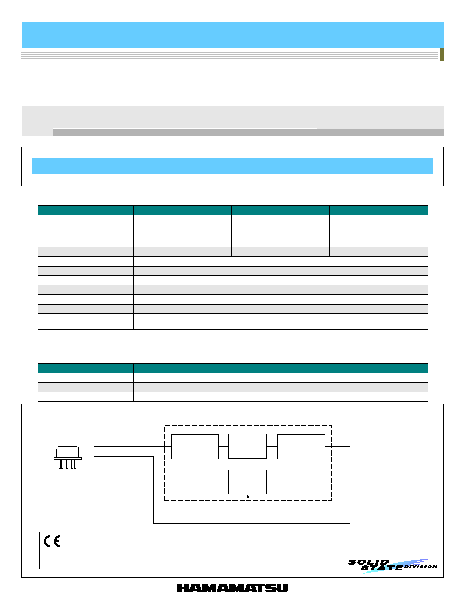
C1103 series is a temperature controller designed for thermoelectrically cooled infrared detectors. C1103 series allows easy but accurate
temperature setting for the thermoelectric cooler mounted in an infrared detector.
Temperature controller
C1103 series
TE-COOLED
DETECTOR
THERMISTOR
TE-COOLED ELEMENT
COMPARATOR
C1103 SERIES
AMP CIRCUIT
CURRENT
CIRCUIT
POWER
SUPPLY
AC INPUT
s Specifications
Parameter
C1103-04
C1103-05
C1103-07
Applicable detector *
1
O n e-stage/two-stage TE-cooled type
P b S, Pb Se p h otoc o n d uctive d etector,
InAs photovoltaic detector,
In G a As, Si, G e ph oto diod e
T wo-stage/three-stage TE-cooled type
M C T, InS b photoconductive detector
One-stage TE-cooled type
M CT, In Sb photoconductive detector
Setting element temperature
-30 to +20 ∞C
-75 to -25 ∞C
-30 to +20 ∞C
Temperature stability
Within ±0.1 ∞C
Te mp erature control output current
1.3 A Max.
Power supply
100 V ± 10 %
∑
50/60 Hz *
2
Power consumption
30 W
Dimensions
105 (W) ◊ 86 (H) ◊ 190 (D) mm
Weight
1.9 kg approx.
Accessories
Instruction manual
4-conductor cable (with a connector, 2 m) A4372-05
*1: It doesn't correspond to infrared detection module with TE-cooled type preamplifier.
*2: Please specify power supply requirement (AC line voltage) from among 100 V, 115 V and 230 V when ordering.
s Absolute maximum ratings
Parameter
Value
Operating temperature
+10 to +40 ∞C
Operating humidity
90 % Max.
Storage temperature
+10 to +40 ∞C
s Block diagram
KIRDC0008EB
KOTHC0005EA
1
C1103-04 conforms to European EMC direc-
tives (89/336/EEC) and LVD (73/23/EEC).

Infrared detector
Accessory
C3871 series is a ±15 V power supply that exhibits minimum ripple and allows accurate
measurements when used with amplifiers for infrared detectors and infrared detector modules
with preamp.
C3871-03 is designed for TE-cooled infrared detector module with preamp.
DC power supply for amplifier
C3871 series
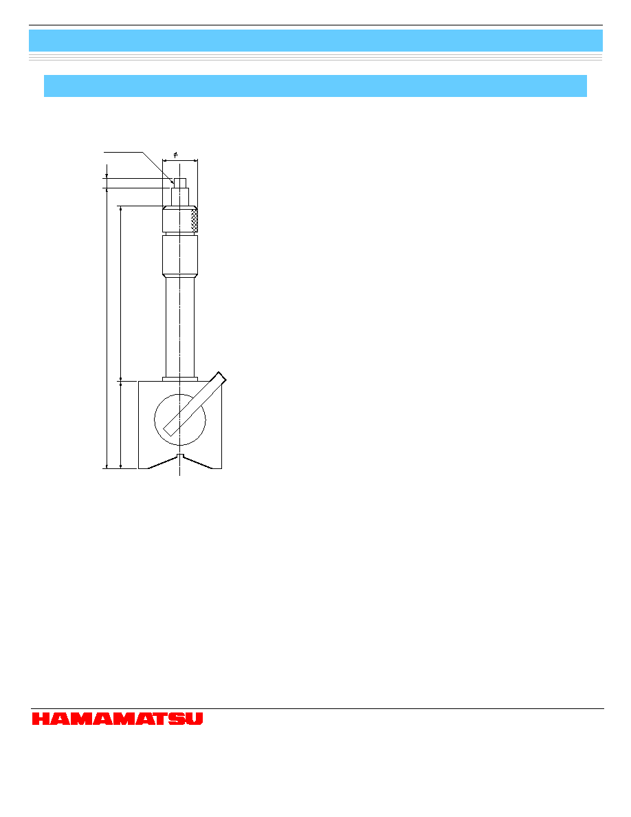
LEAK MOUNT
GLAND NUT
O-RING
80.0
112.5
KNOB
PUMP TUBE
9.5
s Absolute maximum ratings
Parameter
Value
Unit
Power supply
AC 100 V ± 10 %, 50/60 Hz *
-
Operating temperature
-5 to +45
∞C
Storage temperature
-20 to +60
∞C
* Please specify power supply requirement (AC line voltage) from among 100 V, 115 V and 230 V when ordering.
(Typ.)
Parameter
C3871
C3871-03
C3871-04
Unit
Output voltage
± 15 w ith res p e ct to
G N D t er mi n al
±15
2.5
±15
+4.5
V
Output current
Continuous
±150 Max.
Continuous
±150 Max.
Continuous
+2000 Max.
Continuous
±150 Max.
Continuous
+1500 Max.
mA
Input regulation
3
1
25
1
25
mV
Load regulation
5
6
100
6
100
mV
Ripple noise
3
3
25
3
25
mVp-p
Dimensions
75 (W) ◊ 141 (H)
◊ 240 (D)
145 (W) ◊ 142 (H) ◊ 222 (D)
145 (W) ◊ 142 (H) ◊ 222 (D)
mm
Weight
2.2 approx.
3.0 approx.
3.5 approx.
kg
With this valve operator, metal dewars can be re-evacuated to maintain the desired vacuum level. Refer to the instruction manual for details.
Valve operator for metal dewar
A3515
Vacuum pump
Valve operator
Metal dewar type detector
2
KIRDA0021EA
s Dimensional outline (unit: mm)

Infrared detector
Accessory
These heatsinks are designed for use with thermoelectrically cooled detector sealed in a 6-pin TO-8, TO-3 package. The cooling (heat
dissipation) capacity of A3179 and A3179-03 is about 35 ∞C relative to the ambient temperature 25 ∞C, A3179-01 is about 40 ∞C, and that of
A3179-04 is about 85 ∞C. A3179-03 is designed only for two-color detector K3413 series, A3179, A3179-01 for TO-8, A3179-04 for TO-3.
Heatsink for TE-cooled detector (TO-8, TO-3 package)
A3179 series
A3179-01: B=6
A3179-03: B=6.4
Weight: 53 g approx.
32
60∞
40
32
26
46
B
3
36
(4
◊) 3.5
DETECTOR
METAL PACKAGE
PHOTOSENSITIVE
SURFACE *
2
0.4 ± 0.3 *
1
BOTTOM SURFACE
(REFERENCE POINT) OF
DETECTOR METAL PACKAGE
*1: When detector element is installed.
*2: The position of the photosensitive
surface differs according to the
detector element used.
Refer to the dimensional outline for
the detector.
32
60∞
(4
◊) 3.5
3
26
3
0.4 ± 0.3 *
1
Weight: 50 g approx.
32
32.6
46
40
PHOTOSENSITIVE
SURFACE *
2
*1: When detector element is installed.
*2: The position of the photosensitive
surface differs according to the
detector element used.
Refer to the dimensional outline for
the detector.
BOTTOM SURFACE
(REFERENCE POINT) OF
DETECTOR METAL PACKAGE
DETECTOR
METAL PACKAGE
s Dimensional outlines (unit: mm, tolerance unless otherwise noted: ±1)
A3179
A3179-01, A3179-03
A3179-04
56
68
80
56
40
45
PHOTOSENSITIVE
SURFACE
6.7 ± 0.5
3
±
0.5
38
±
0.5
(4 ◊) 3.5 ± 0.5
FIXATION BOARD
19.7
+1
-0
Weight: 320 g approx.
KIRDA0149EB
KIRDA0018EB
KIRDA0019EB
3

Infrared detector
Accessory
Chopper
C4696
18
13.5
38.5
BNC
A1447
(MAGNET STAND)
23.0 45.0
19
202.3 TO 272.3 (ADJUSTABLE)
OUTPUT
WINDOW
8.0
INPUT WINDOW
4.0
12.5
17.5
30
+12 V
ON-OFF
GND
6-PIN RECEPTACLE
CORD LENGTH: 2 m
(FOR CONNECTION
TO DRIVER CIRCUIT)
12.5
25
37
60
6-PIN CONNECTOR
TRIG
COUNTER
85
88
<CHOPPER>
<DRIVER CIRCUIT>
s Specifications
Parameter
Specification
Chopping frequency *
1
115 to 380 Hz, 345 Hz Typ. *
2
Power supply (V
D
)
DC 5 to 13 V, 12 V Typ.
Duty ratio
1: 1
Rotational stability
0.06 %/∞C
Min.
V
D
- 0.5 V
Sync signal
(high level)
Max.
V
D
- 0.2 V
Operating temperature
0 to 50 ∞C
Maximum current consumption *
2
90 mA
Accessory
Magnet stand A1447
*1: Chopping frequency will be 230 to 760 Hz when an optional disc is used.
*2: V
D
=12 V
s Dimensional outline (unit: mm)
KIRDA0022EA
4
Infrared detector
Accessory
Magnet stand
A1447
HAMAMATSU PHOTONICS K.K., Solid State Division
1126-1 Ichino-cho, Hamamatsu City, 435-8558 Japan, Telephone: (81) 053-434-3311, Fax: (81) 053-434-5184, http://www.hamamatsu.com
U.S.A.: Hamamatsu Corporation: 360 Foothill Road, P.O.Box 6910, Bridgewater, N.J. 08807-0910, U.S.A., Telephone: (1) 908-231-0960, Fax: (1) 908-231-1218
Germany: Hamamatsu Photonics Deutschland GmbH: Arzbergerstr. 10, D-82211 Herrsching am Ammersee, Germany, Telephone: (49) 08152-3750, Fax: (49) 08152-2658
France: Hamamatsu Photonics France S.A.R.L.: 8, Rue du Saule Trapu, Parc du Moulin de Massy, 91882 Massy Cedex, France, Telephone: 33-(1) 69 53 71 00, Fax: 33-(1) 69 53 71 10
United Kingdom: Hamamatsu Photonics UK Limited: 2 Howard Court, 10 Tewin Road, Welwyn Garden City, Hertfordshire AL7 1BW, United Kingdom, Telephone: (44) 1707-294888, Fax: (44) 1707-325777
North Europe: Hamamatsu Photonics Norden AB: Smidesv‰gen 12, SE-171 41 Solna, Sweden, Telephone: (46) 8-509-031-00, Fax: (46) 8-509-031-01
Italy: Hamamatsu Photonics Italia S.R.L.: Strada della Moia, 1/E, 20020 Arese, (Milano), Italy, Telephone: (39) 02-935-81-733, Fax: (39) 02-935-81-741
Information furnished by HAMAMATSU is believed to be reliable. However, no responsibility is assumed for possible inaccuracies or omissions.
Specifications are subject to change without notice. No patent rights are granted to any of the circuits described herein. ©2001 Hamamatsu Photonics K.K.
Cat. No. KACC1062E04
Nov. 2001 DN
1/4-20UNC
100
20
49.5
160 MIN. 230 MAX.
5.5
s Dimensional outline (unit: mm)
KIRDA0017EA
5