 | –≠–ª–µ–∫—Ç—Ä–æ–Ω–Ω—ã–π –∫–æ–º–ø–æ–Ω–µ–Ω—Ç: C6245 | –°–∫–∞—á–∞—Ç—å:  PDF PDF  ZIP ZIP |
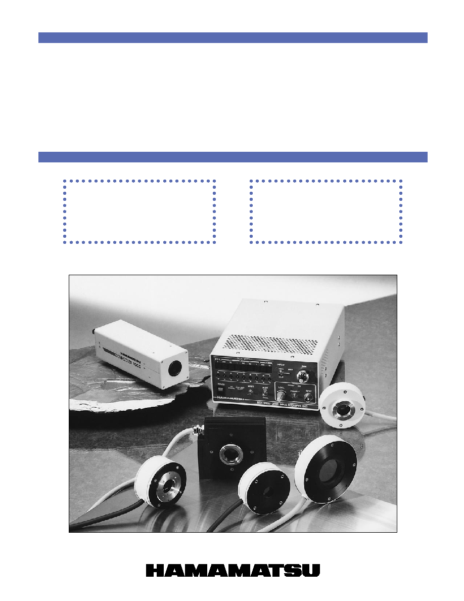
HIGH-SPEED GATED
IMAGE INTENSIFIER UNITS
ICCD CAMERA UNITS
SELECTION
GUIDE
APPLICATION
NOTES

CONTENTS
Capturing "Instantaneous Images" of High-speed Phenomena 1
Hints to Selecting Products .......................................................... 2
Principle .......................................................................................... 3
Selection Guide .............................................................................. 4
Specifications ................................................................................. 6
Dimensions ..................................................................................... 7
1
C7068-01, C7069-01 .............................................................................................. 7
2
C6653, C6654, C7786, C7787 ................................................................................ 7
3
C7245, C7244 ......................................................................................................... 7
4
C2925-01, C4078-01 .............................................................................................. 7
5
C6245 ..................................................................................................................... 8
6
C5909, -10, -12 ....................................................................................................... 8
7
C5909-06, -08 ......................................................................................................... 8
8
C5825 ..................................................................................................................... 9
Readout Methods ......................................................................... 10
Readout Device Selection Guide ................................................ 10
Application Note ........................................................................... 12
1
The high-speed gated image intensifier (hereafter referred to as the gate I.I.)
is capable of capturing "instantaneous images" of high-speed phenomena in
an extremely short period of time, using "gate operation" (or shutter opera-
tion).
For instance, to analyze an automotive engine turning at a speed of 6,000
rpm would require fast analysis at 1/10000 of a second or less. The gate I.I.
can capture the "instantaneous images" in this kind of analysis.
Gate operation is the same as the shutter operation of a camera, but in the
gate I.I. it is carried out electrically. In the example below, gating is being done
at 3 ns. (The 3 ns time period is equivalent to light advancing 90 cm at a speed
of 300,000 kilometers per second.) By synchronizing the gate operation to a
laser or similar light source extraneous, light outside the measurement target
such as background light and excitation light can be eliminated.
The gate I.I. has an internal image enhancement function, and is available in
two types, one with a single-stage microchannel plate (MCP) and one with a
two-stage MCP for applications requiring even higher image intensification.
A short gate time may result in an insufficient amount of light which enters the
image camera. In this case, better images can be obtained using an image
enhancement unit which enables image integration, and an image booster
unit which compensates for insufficient light.
There are two types of gate I.I. available: a gate I.I. unit with which the user
can select the camera to be used for readout, and an ICCD camera unit which
combines a gate I.I. with a CCD camera. In addition to imaging in the visible
light region, gated X-ray image intensifiers are also available to capture "in-
stantaneous images" of X-ray phenomena.
Applications
q
Engine combustion state analysis
q
Monitoring of kinetic changes in
plasma emissions
q
Imaging of turbine blades
q
Imaging of exploding events
q
Imaging of gaseous and liquid bodies
moving at high speed
q
Imaging of objects moving at high
speed
q
Imaging of fluorescence lifetime
q
Low-light-level bioluminescence/
chemiluminescence imaging
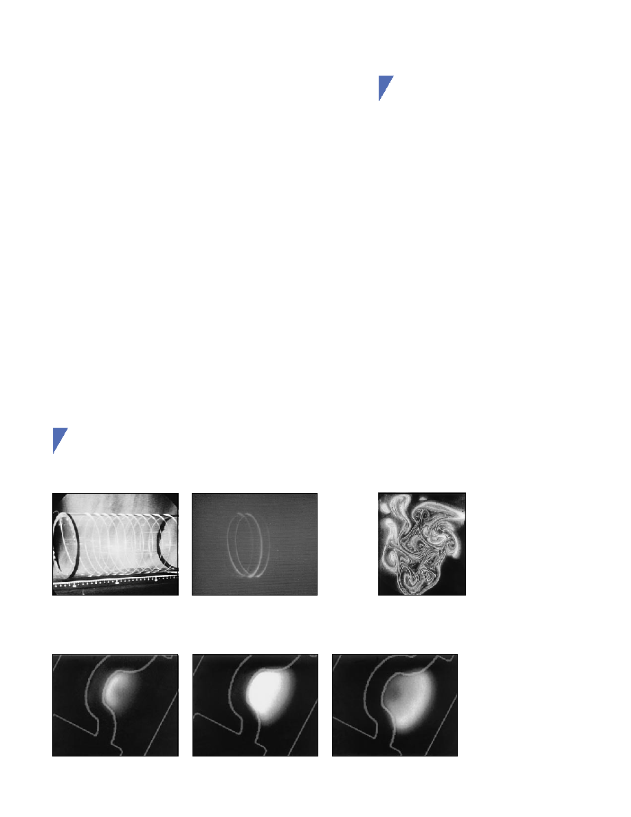
Imaging Examples
q
Observation of pulsed light propagation through optical fiber
Laser pulse light movements can be observed within the gate time.
q
Imaging of cross-section of jet flame
Turbulent eddies in an ethylene jet flame can be observed.
Wavelength : 550 nm
Pulse width : 50 ps
0.47
µ
s
after pulsed voltage is applied
0.71
µ
s
after pulsed voltage is applied
1.09
µ
s
after pulsed voltage is applied
Gate time
: 100 ns
Integrated image
Experimental setup of optical fiber
Gate time : 3 ns
Wavelength : 530 nm
Pulse width : 10 ns
Gate time
: 100 ns
Capturing "Instantaneous Images" of High-speed Phenomena
Capturing "Instantaneous Images" of High-speed Phenomena
For details, please see page 15.
q
Kinetic changes in plasma emissions
Kinetic changes in the emissions from an electrode of a plasma display panel (PDP) can be observed.
For details, please see page 13.
For details, please see last page.

2
Description
This is the time required to capture one image. "Instantaneous
images" of phenomena occurring within this gate time can be
captured. If the gate time is shortened, images with little move-
ment can still be captured, but there is less light, so that a
darker image results. (A unit with a gate time appropriate for
the measurement target should be selected.)
This is the number of gate operations in 1 second. This also
depends on the repetition frequency of the object being meas-
ured and the number of frames of the camera being used.
The higher the quantum efficiency (conversion efficiency from
input light into photoelectrons), the smaller the flicker that ap-
pears in the obtained image.
GaAs photocathodes have higher quantum efficiency than
multialkali photocathodes over a wide spectral range from 450
to 900 nm.
This is the factor which determines the image intensification
level and the resulting detection limit. With ordinary CCD cam-
eras, the limit for imaging is around 0.1 lux. The intensifier unit
may have either a 1-stage or a 2-stage MCP. With the 1-stage
MCP type, the image is enhanced around 10,000 times, ena-
bling images to be captured at low-light-levels of 1
◊
10
-5
lux.
With the 2-stage MCP type, images are enhanced approxi-
mately one million times, and can be captured at even lower
light levels of 1
◊
10
-7
lux. The two-stage MCP type offers sen-
sitivity that enables detection at single-photon level.
The light levels noted above are for a gate time of 1 second.
The relative quantity of light decreases as the gate time short-
ens, so it is necessary to increase the quantity of incident light.
This is the factor which determines the resolution.
The size of the effective input surface is determined by the
desired resolution* of the output image and the size of the inci-
dent image. The image resolution degrades as the quantity of
incident light decreases.
Selection Method
Select the disired gate time according to
the time period during which images are
to be captured.
Select the repetition frequency depend-
ing on how many images are to be cap-
tured per second.
What is the spectral range to be detected.
-UV to visible range
Use a multialkali photocathode.
-Near IR range
Use a GaAs photocathode.
GaAs photocathodes are recommended
in a spectral range of 800 to 900 nm.
When monitoring candlelight:
q
Gate time : less than 1
µ
s ... 2-MCP type
more than 5
µ
s .... 1-MCP type
The above numeric values are general guides, and
are affected by conditions such as the light level, gate
time, image intensification (gain), lens, imaging de-
vice, and other factors. Please consult Hamamatsu
regarding details.
q
Commercial CCD camera (about
400,000 pixels) or
high-speed camera ...............
18 mm
q
High-resolution CCD camera ... 40 mm
Item
Gate time
Gate repetition
frequency
Photocathode
sensitivity
Stage of MCPs
Effective output
size
Hints to
Selecting
Products
The guidelines listed below help you select a gate I.I. with the optimum specifications for the
measurement.
The five items noted below are especially important when selecting a product, and products
can be selected by considering these five factors in combination.
* To improve the resolution
The resolution of a gate I.I. unit depends on the surface area of the output phosphor screen, because the minimum luminous spot
size on the phosphor screen is limited to 30 to 50
µ
m. This means that higher resolution can be obtained by using a larger phosphor
screen and focusing the image onto the CCD through an optical lens with a high reduction ratio.
On the other hand, GaAs photocathode types provide a higher resolution because of the characteristics of photocathode itself.

3
HIGH-SPEED GATED IMAGE INTENSIFIER UNIT
This is configured of a proximity focused image intensifier and a high-
voltage power supply with a gate control circuit. A CCD camera with an
FOP window, a CCD camera, a high-speed camera, or a similar device
may be selected as the camera.
ICCD CAMERA UNIT
Proximity focused image intensifier
HIGH-SPEED GATED IMAGE INTENSIFIER UNIT
Principle
Internal Structure
Proximity focused image intensifier structure
Gating operation
(Proximity-focused image intensifier)
POWER SUPPLY
HEAD
PROXIMITY FOCUSED
IMAGE INTENSIFIER
HIGH-SPEED GATE
DRIVE CIRCUIT
INCIDENT
LIGHT
OUTPUT
LIGHT
GATE CONTROL
CIRCUIT
LOW-VOLTAGE
POWER SUPPLY
CIRCUIT
HIGH-VOLTAGE POWER
SUPPLY/CONTROL CIRCUIT
FOR IMAGE INTENSIFIER
TAPPC0047EA
CCD DRIVE
CIRCUIT
HIGH-
VOLTAGE
POWER
SUPPLY/
CONTROL
CIRCUIT FOR
IMAGE
INTENSIFIER
HIGH-SPEED
GATE DRIVE
CIRCUIT/
CONTROL
CIRCUIT
LOW-VOLTAGE
POWER SUPPLY
CIRCUIT
PROXIMITY FOCUSED IMAGE INTENSIFIER
C-MOUNT
FIBER OPTIC PLATE
CCD
INCIDENT
LIGHT
VIDEO
SIGNAL
TAPPC0048EA
OUTPUT
WINDOW
(FIBER
PLATE)
PHOSPHOR SCREEN
(ELECTRON LIGHT)
PHOTO-
CATHODE
MCP
(ELECTRON
MULTIPLICATION)
INPUT
WINDOW
(LIGHT
PHOTOELECTRON)
TII C0046EA
MCP
V
MCP
V
B
V
S
GATE ON
PULSE
LIGHT
LIGHT
V
G
PULSE
GENERATOR
PHOTOCATHODE
PHOSPHOR
SCREEN
PHOTOELECTRONS
ELECTRONS
C
R
0
≠200V
0V
ex.: V
B
= +30V
V
G
= ≠230V
TII C0047EA
MCP
V
MCP
V
B
V
S
C
R
PHOSPHOR SCREEN
PHOTOELECTRONS
PHOTOCATHODE
LIGHT
PULSE
GENERATOR
+30V
0V
TII C0048EA
Gate OFF
Gate ON
The light incident on the photocathode is converted to photoelectrons which are guided to
the phosphor screen by an electric potential gradient. Gating is done by instantly chang-
ing the electric potential of the electrodes in the image intensifier.
Gating with the proximity-focused image intensifier
This is done by changing the electric potential between the photocathode and the MCP.
q
If the MCP potential is higher than the photocathode potential: Gate is ON
The photoelectron image converted by the photocathode is pulled to the MCP at a
high electric potential. After multiplication in the MCP, the electron image is than guided
to the output phosphor screen where it is output as an optical image.
q
If the MCP potential is lower than the photocathode potential: Gate is OFF
The photoelectron image converted by the photocathode is repelled away from the
MCP at a low electric potential, and operation is interrupted at this point.
Gate operation
A proximity forcused image intensifier is an image device that is capable of enhancing a
low-light-level image from several thousands to several millions of times.
The optical image input to the image intensifier is converted to photoelectrons at the
photocathode. The photoelectrons are drawn by an electrical field and enter a microchannel
plate (MCP) where they repeatedly impinge on the inner wall more than ten times. Each
time an electron impinge on the wall, secondary electrons are released, so that the total
number of electrons is multiplied several thousands of times. The electrons then strike the
phosphor screen and are converted back into an optical image. With a 2-stage MCP type,
optical images can be enhanced several millions of times.
This is configured of a proximity focused image intensifier with an in-
corporated CCD.