
A7
3.96mm and 4mm Pitch Card Edge Connector
CR7 Series
s
Product Specifications
Rating
Current rating: 3A
Voltage rating: 600V AC
Operating Temperature Range:
-
30
to
+85
Á (Note 1)
Operating Humidity Range: 40
to
80
%
Storage Temperature Range:
-
10
to
+60
Á (Note 2)
Storage Humidity Range: 40
to
70
%
(Note 2)
Note 1: Includes temperature rise caused by current flow.
Note 2: The term "storage" refers to products stored for long period of time prior to mounting and use. Operating Temperature Range and
Humidity range covers non conducting condition of installed connectors in storage, shipment or during transportation.
500V DC
1800V AC/1 minute
100mA
Frequency: 10 to 55 Hz, single amplitude of 0.75 mm, 2 hours in each of the 3 directions.
96 hours at temperature of 40Á and humidity of 90% to 95%
500 cycles
Manual soldering: 300Á for 3 seconds
5000M
ohms
No flashover or insulation breakdown.
15m ohms max.
No electrical discontinuity of 10µs or more
Insulation resistance: 1000M min.
Contact resistance: 15m
ohms
max.
No deformation of components affecting performance.
No damage, cracks, or parts looseness.
(-55
Á
: 30 minutes
°
15 to 35
Á
: 5 minutes max.
°
85
Á
: 30 minutes
°
15 to 35
Á
: 5 minutes max.) 5 cycles
1.Insulation Resistance
2.Withstanding Voltage
3.Contact Resistance
4.Vibration
5.
Humidity (Steady state)
6.Temperature Cycle
7.Durability (Mating/un-mating)
8.Resistance to Soldering heat
Connection Type
Eyelet
Through hole
s
Features
1. Contact Type
Uses 2 steps of bellows type
contact, where the contact
pitch is 3.96mm or 4mm.
2. Variation in number of contacts
12, 20, 28, 30, 36, 44, 56, 72 and 80 contacts are
available.
3. Connection Type
Eyelet and through hole types are available.
4. Prevents mis-insertion in the board
Using the polarizing key prevents mis-insertion in the
printed board.
Item
Specification
Condition

A8
s
Material
s
Ordering Information
CR7 C ≠ 20 D B ≠ 4 E
q
e
w
r
t
y u
(1) Eyelet
(2) Through hole
r
Contact alignment : D:Double side
t
Contact Type
B : Selective gold plated
y
Contact pitch
: 4mm or 3.96mm
u
Contact style
E : Eyelet
DS : Through hole
q
Series Name
: CR7
w
Mold type
: C : 4mm pitch mold
E
: 3.96mm pitch mold
e
Number of contacts : C : 20, 28, 36, 44, 56
E : 12, 20, 30, 36, 44, 56, 72, 80
B
Contact Type
Insulator
Contact
Polycarbonate
Copper alloy
Selective gold plated
Tin-lead plated
Blue
Contact area
Lead area
UL94V-0
________
________
Parts
Material
Finish
Remarks
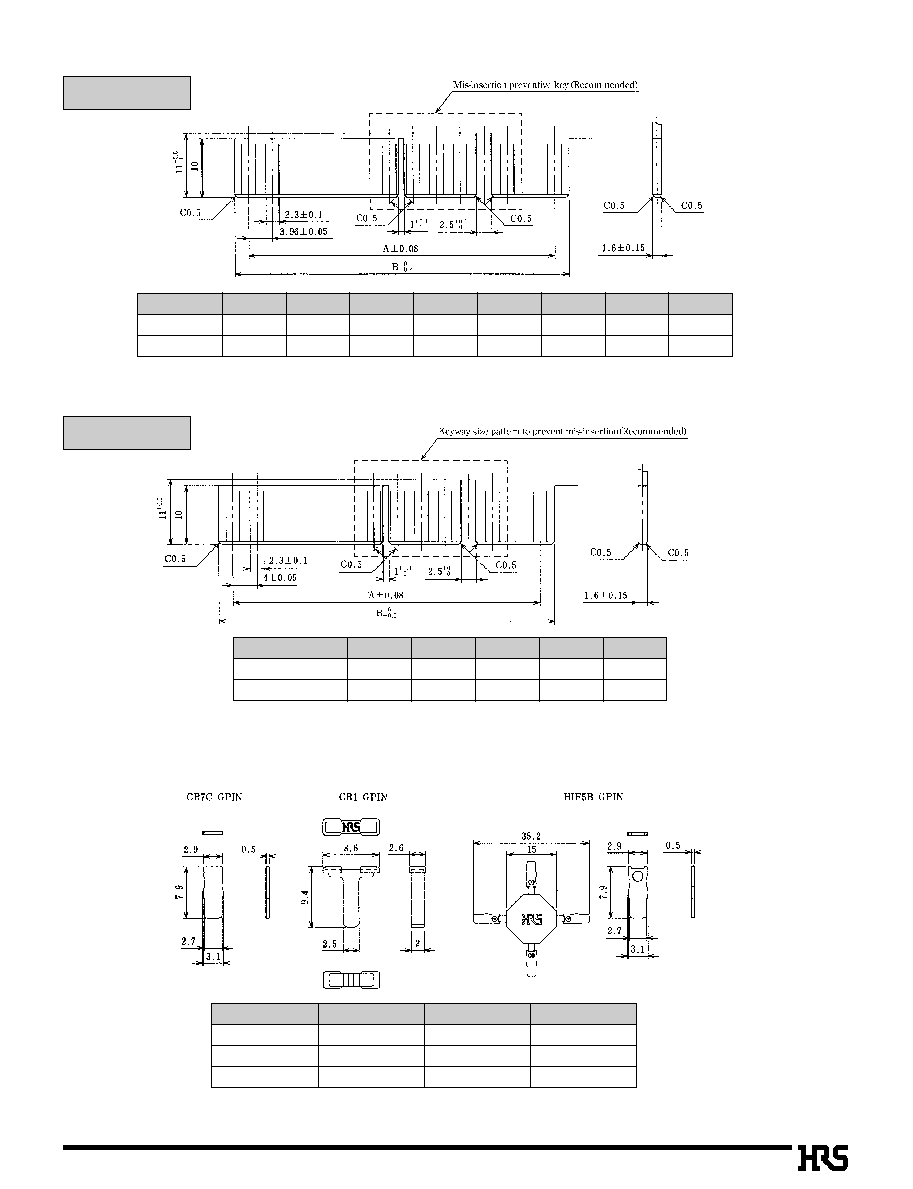
A11
B
PCB Dimensions
s
Polarizing Key
12
20
30
36
44
56
72
80
A
B
19.8
27.8
35.64
43.6
0
55.44
63.4
0
67.32
75.3
0
83.16
91.2
0
106.98
114.8
0
138.68
146.6
0
154.44
162.5
0
4mm pitch
Note: Using the polarizing key prevents mis-insertion in the printed board.
To use the polarizing key, insert the polarizing key so as to hit the mold bottom.
Number of Contacts
20
28
36
44
56
A
B
36
.0
40.8
52
.0
56.8
68
.0
72.8
84
.0
88.8
108
.0
107.8
Note: Using the polarizing key prevents mis-insertion in the printed board.
To use the polarizing key, insert the polarizing key so as to hit the mold bottom.
Number of Contacts
Part Number
CL No.
Material
Color
507-0055-8
501-0030-9
564-0052-4
CR7C-GPIN
CR1-GPIN
HIF5B-GPIN
Poly-acetal
ABS
PBT
White
Gray
Beige
3.96 pitch


