
12
M
I
X
E
R
S
- SM
T
12 - 72
For price, delivery, and to place orders, please contact Hittite Microwave Corporation:
20 Alpha Road, Chelmsford, MA 01824 Phone: 978-250-3343 Fax: 978-250-3373
Order On-line at www.hittite.com
HMC214MS8
/
214MS8E
HIGH IP3 GaAs MMIC
MIXER, 2.4 - 4.0 GHz
v00.0205
General Description
Features
Functional Diagram
+34 dBm Input IP3
28 dB LO to RF Isolation
+22 dBm Input P1dB
No External Components
Ultra Small MSOP Package: 14.8mm
2
Electrical Specifications,
T
A
= +25�C, LO = +17dBm, IF = 200 MHz*
Typical Applications
The HMC214MS8 / HMC214MS8E is ideal for:
� WiMAX, 802.16
� Fixed Wireless Access
� Wireless Local Loop
*Unless otherwise noted, all measurements performed as a downconverter, with low side LO & IF = 200 MHz.
The HMC214MS8 & HMC214MS8E are general
purpose high dynamic range passive MMIC mixers
in plastic surface mount 8 lead Mini Small Outline
Packages (MSOP) covering 2.4 to 4 GHz. Excel-
lent input IP3 performance of +34 dBm for downcon-
version and +31 dBm for upconversion is provided
for WiMax and other 3.5 GHz applications at an
LO drive of +17 dBm. With a 1dB compression of
+22 dBm, the RF port will accept a wide range of
input signal levels. Conversion loss is 10 dB typi-
cal and LO isolations are maintained at 25 to 30 dB.
This miniature single-ended monolithic GaAs FET
mixer does not require any external components or
bias. The DC to 1 GHz IF frequency response will
satisfy many transmit and receive frequency plans
confi gured for low side LO. The HMC214MS8 &
HMC214MS8E input IP3 performance coupled with
its high P1dB rivals traditional active FET mixers
while offering a much smaller 14.8mm
2
standard IC
footprint and no DC bias.
Parameter
Min.
Typ.
Max.
Min.
Typ.
Max.
Units
Frequency Range, RF
2.4 - 4.0
3.4 - 3.8
GHz
Frequency Range, LO
2.4 - 4.0
3.4 - 3.8
GHz
Frequency Range, IF
DC - 1
DC - 1
GHz
Conversion Loss
10
12
10
11.5
dB
Noise Figure (SSB)
10
12
10
11.5
dB
LO to RF Isolation
18
30
20
28
dB
LO to IF Isolation
12
25
22
30
dB
IP3 (Input)
26
30
31
34
dBm
1 dB Gain Compression (Input)
18
21
20
22
dBm
LO Input Drive Level (Typical)
+15 to +19
+15 to +19
dBm

12
M
I
X
E
R
S
- SM
T
12 - 73
For price, delivery, and to place orders, please contact Hittite Microwave Corporation:
20 Alpha Road, Chelmsford, MA 01824 Phone: 978-250-3343 Fax: 978-250-3373
Order On-line at www.hittite.com
Conversion Gain vs.
Temperature @ LO = +17 dBm
Isolation @ LO = +17 dBm
Conversion Gain vs. LO Drive
Return Loss @ LO = +17 dBm
IF Bandwidth @ LO = +17 dBm
Upconverter Performance
Conversion Gain @ LO = +17 dBm
Unless otherwise noted, all measurements performed as a downconverter, with low side LO & IF = 200 MHz.
-20
-15
-10
-5
0
2.2
2.4
2.6
2.8
3
3.2
3.4
3.6
3.8
4
4.2
+25 C
+85 C
-40 C
CONVERSION GAIN (dB)
RF FREQUENCY (GHz)
-40
-30
-20
-10
0
2.2
2.4
2.6
2.8
3
3.2
3.4
3.6
3.8
4
4.2
RF to IF
LO to RF
LO to IF
ISOLATION (dB)
FREQUENCY (GHz)
-25
-20
-15
-10
-5
0
2.2
2.4
2.6
2.8
3
3.2
3.4
3.6
3.8
4
4.2
RF
LO
RETURN LOSS (dB)
FREQUENCY (GHz)
-20
-15
-10
-5
0
2.2
2.4
2.6
2.8
3
3.2
3.4
3.6
3.8
4
4.2
CONVERSION GAIN (dB)
RF FREQUENCY (GHz)
-20
-15
-10
-5
0
2.2
2.4
2.6
2.8
3
3.2
3.4
3.6
3.8
4
4.2
LO = +15 dBm
LO = +16 dBm
LO = +17 dBm
LO = +19 dBm
CONVERSION GAIN (dB)
RF FREQUENCY (GHz)
-20
-15
-10
-5
0
0
0.1
0.2
0.3
0.4
0.5
0.6
0.7
0.8
0.9
1
Conver. Gain
Return Loss
RESPONSE (dB)
IF FREQUENCY (GHz)
HMC214MS8
/
214MS8E
HIGH IP3 GaAs MMIC
MIXER, 2.4 - 4.0 GHz
v00.0205

12
M
I
X
E
R
S
- SM
T
12 - 74
For price, delivery, and to place orders, please contact Hittite Microwave Corporation:
20 Alpha Road, Chelmsford, MA 01824 Phone: 978-250-3343 Fax: 978-250-3373
Order On-line at www.hittite.com
Input IP3 vs.
Temperature, LO = +17 dBm
Input IP3 vs. LO Drive
Upconverter IP3 vs.
LO Drive, IF = 200 MHz
Input P1dB vs.
Temperature @ LO = +17 dBm
Unless otherwise noted, all measurements performed as a downconverter, with low side LO & IF = 200 MHz.
20
25
30
35
40
2.2
2.4
2.6
2.8
3
3.2
3.4
3.6
3.8
4
4.2
LO = +15 dBm
LO = +16 dBm
LO = +17 dBm
LO = +19 dBm
INPUT IP3 (dBm)
RF FREQUENCY (GHz)
20
25
30
35
40
45
2.2
2.4
2.6
2.8
3
3.2
3.4
3.6
3.8
4
4.2
LO = +15 dBm
LO = +16 dBm
LO = +17 dBm
LO = +19 dBm
INPUT IP3 (dBm)
RF FREQUENCY (GHz)
20
25
30
35
40
45
2.2
2.4
2.6
2.8
3
3.2
3.4
3.6
3.8
4
4.2
+25 C
+85 C
-40 C
INPUT IP3 (dBm)
RF FREQUENCY (GHz)
15
16
17
18
19
20
21
22
23
24
25
2.2
2.4
2.6
2.8
3
3.2
3.4
3.6
3.8
4
4.2
+25 C
+85 C
-40 C
INPUT P1dB (dBm)
RF FREQUENCY (GHz)
HMC214MS8
/
214MS8E
HIGH IP3 GaAs MMIC
MIXER, 2.4 - 4.0 GHz
v00.0205
MxN Spurious Outputs
nLO
mRF
0
1
2
3
4
0
xx
-4
-2
9
xx
1
9
0
37
39
35
2
73
66
49
65
77
3
97
98
104
85
91
4
xx
100
99
104
106
RF Freq = 3.5 GHz @ -10 dBm
LO Freq = 3.3 GHz @ +17 dBm
All values in dBc relative to the IF output power.
Harmonics of LO
nLO Spur @ RF Port
LO Freq (GHz)
1
2
3
4
2.6
35
26
42
39
2.8
30
26
47
40
3.0
29
26
46
42
3.2
28
29
42
xx
3.4
25
28
40
xx
3.6
24
31
39
xx
LO = +17 dBm
All values are in dBc below input LO level @ RF port.
12
M
I
X
E
R
S
- SM
T
12 - 75
For price, delivery, and to place orders, please contact Hittite Microwave Corporation:
20 Alpha Road, Chelmsford, MA 01824 Phone: 978-250-3343 Fax: 978-250-3373
Order On-line at www.hittite.com
Unless otherwise noted, all measurements performed as a downconverter, with low side LO & IF = 200 MHz.
Absolute Maximum Ratings
ELECTROSTATIC SENSITIVE DEVICE
OBSERVE HANDLING PRECAUTIONS
RF/IF Input
+27 dBm
LO Drive
+27 dBm
IF DC Current
�40 mA
Channel Temperature
150 �C
Continuous Pdiss (T=85 �C)
(derate 3.69 mW/�C above 85 �C)
240 mW
Thermal Resistance (R
TH
)
(junction to lead)
270 �C/W
Storage Temperature
-65 to +150 �C
Operating Temperature
-40 to +85 �C
HMC214MS8
/
214MS8E
HIGH IP3 GaAs MMIC
MIXER, 2.4 - 4.0 GHz
v00.0205
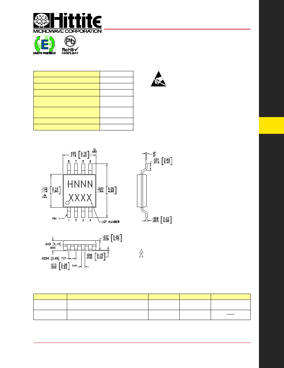
Outline Drawing
NOTES:
1. LEADFRAME MATERIAL: COPPER ALLOY
2. DIMENSIONS ARE IN INCHES [MILLIMETERS]
3. DIMENSION DOES NOT INCLUDE MOLDFLASH OF 0.15mm PER SIDE.
4. DIMENSION DOES NOT INCLUDE MOLDFLASH OF 0.25mm PER SIDE.
5. ALL GROUND LEADS MUST BE SOLDERED TO PCB RF GROUND.
Part Number
Package Body Material
Lead Finish
MSL Rating
Package Marking
[3]
HMC214MS8
Low Stress Injection Molded Plastic
Sn/Pb Solder
MSL1
[1]
H214
XXXX
HMC214MS8E
RoHS-compliant Low Stress Injection Molded Plastic
100% matte Sn
MSL1
[2]
H214
XXXX
[1] Max peak refl ow temperature of 235 �C
[2] Max peak refl ow temperature of 260 �C
[3] 4-Digit lot number XXXX
Package Information
12
M
I
X
E
R
S
- SM
T
12 - 76
For price, delivery, and to place orders, please contact Hittite Microwave Corporation:
20 Alpha Road, Chelmsford, MA 01824 Phone: 978-250-3343 Fax: 978-250-3373
Order On-line at www.hittite.com
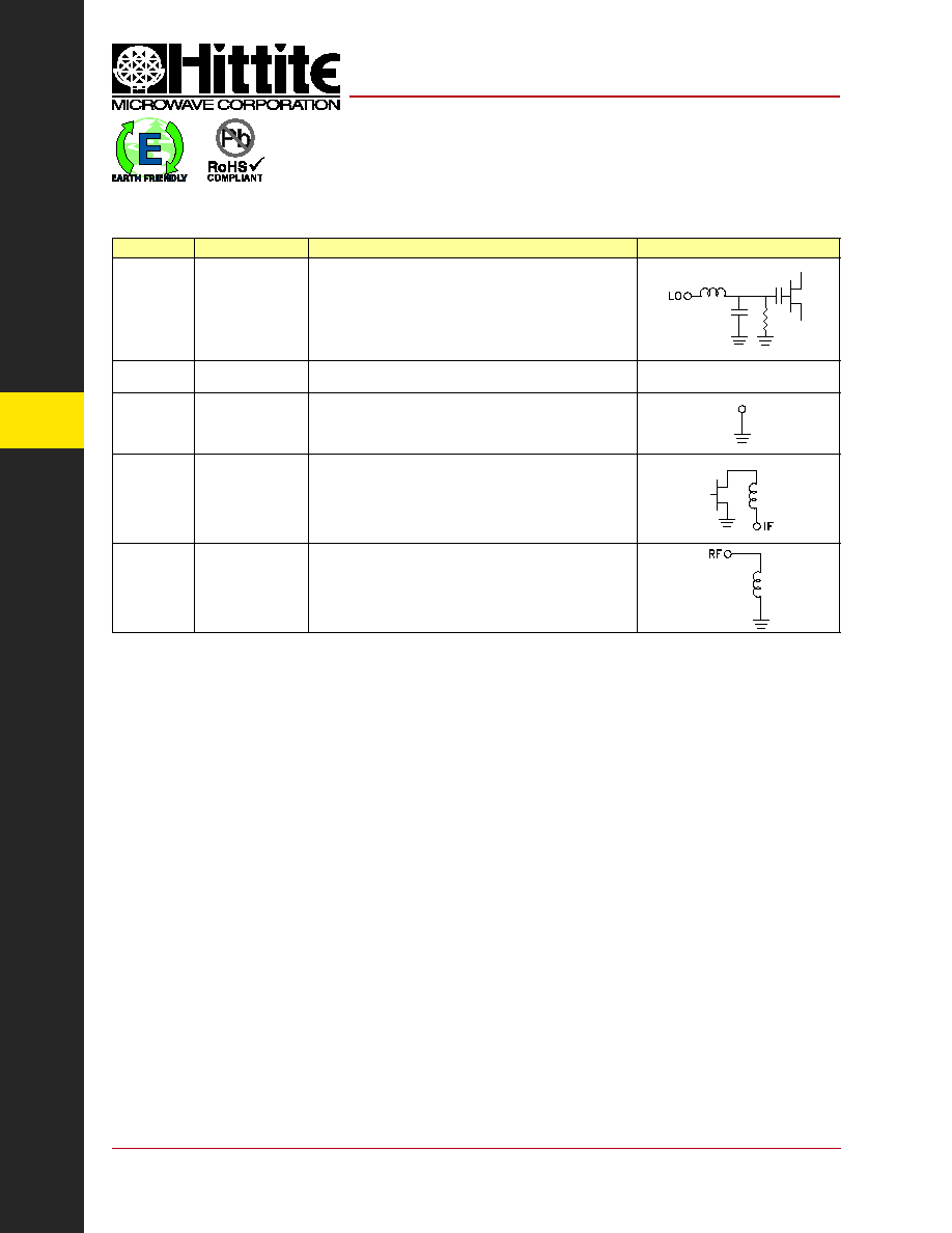
Pin Number
Function
Description
Interface Schematic
1
LO
This pin is DC coupled & matched to 50 Ohms
from 2.4 to 4.0 GHz. Blocking capacitors are required if line
potential is not equal to 0V.
2, 4
N/C
No connection. These pins may be connected to RF ground.
Performance will not be affected.
3, 6, 7
GND
This pin must be connected to RF ground.
5
IF
This pin is DC coupled. For applications not requiring operation
to DC this port should be DC blocked externally using a series
capacitor. Choose value of capacitor to pass IF frequency
desired. For operation to DC, this pin must not sink/source
more than 40 mA of current or failure may result.
8
RF
This pin is DC coupled & matched to 50 Ohm
from 2.4 to 4.0 GHz
Pin Descriptions
HMC214MS8
/
214MS8E
HIGH IP3 GaAs MMIC
MIXER, 2.4 - 4.0 GHz
v00.0205