 | –≠–ª–µ–∫—Ç—Ä–æ–Ω–Ω—ã–π –∫–æ–º–ø–æ–Ω–µ–Ω—Ç: HMC265LM3 | –°–∫–∞—á–∞—Ç—å:  PDF PDF  ZIP ZIP |

MICROWAVE CORPORATION
12 - 94
For price, delivery, and to place orders, please contact Hittite Microwave Corporation:
12 Elizabeth Drive, Chelmsford, MA 01824 Phone: 978-250-3343 Fax: 978-250-3373
Order Online at www.hittite.com
MIXERS - SMT
12
HMC265LM3
GaAs MMIC SUB-HARMONIC
SMT MIXER, 20 - 31 GHz
v01.1201
General Description
Features
Functional Diagram
The HMC265LM3 is a 20 - 31 GHz surface mount
sub-harmonically pumped (x2) MMIC mixer down-
converter with integrated LO and IF amplifi ers in
a SMT leadless chip carrier package. The 2LO to
RF and IF isolations are an excellent 28 to 47 dB,
eliminating the need for additional fi ltering. The
LO amplifi er is a single bias (+3V to +4V) two
stage design with only -4 dBm drive requirement.
All data is with the non-hermetic, epoxy sealed
LM3 packaged device mounted in a 50 ohm test
fi xture. Utilizing the HMC265LM3 eliminates the
need for wirebonding, thereby providing a con-
sistent connection interface for the customer.
Integrated LO Amplifi er: -4 dBm Input
Sub-Harmonically Pumped (x2) LO
High 2LO/RF Isolation: > 28 dB
LM3 SMT Package
Electrical Specifi cations,
T
A
= +25∞ C, As a Function of Vdd
Typical Applications
The HMC265LM3 is ideal for:
∑ 20 and 31 GHz Microwave Radios
∑ Downconverter for Point to Point Radios
∑ LMDS and SATCOM
*Unless otherwise noted, all measurements performed as downconverter, IF= 2 GHz.
Parameter
IF = 2 GHz
LO = -4 dBm & Vdd = +4V
IF = 2 GHz
LO = -4 dBm & Vdd = +4V
IF = 2 GHz
LO = -4 dBm & Vdd = +3V
Units
Min.
Typ.
Max.
Min.
Typ.
Max.
Min.
Typ.
Max.
Frequency Range, RF
20 - 31
27 - 30
21 - 30
GHz
Frequency Range, LO
10 - 15.5
13.5 - 15
10.5 - 15
GHz
Frequency Range, IF
0.7 - 3
0.7 - 3
0.8 - 2.8
GHz
Conversion Gain (RF to IF)
-2
3
0
4
-1
3
dB
Noise Figure (SSB)
13
13
13
dB
2LO to RF Isolation
21
28
28
35
20
28
dB
2LO to IF Isolation
39
47
40
48
38
47
dB
IP3 (Input)
2
8
6
10
2
8
dBm
1 dB Compression (Input)
-1
+2
0
+3
0
dBm
Supply Current (Idd)
50
50
40
mA

MICROWAVE CORPORATION
12 - 95
For price, delivery, and to place orders, please contact Hittite Microwave Corporation:
12 Elizabeth Drive, Chelmsford, MA 01824 Phone: 978-250-3343 Fax: 978-250-3373
Order Online at www.hittite.com
MIXERS - SMT
12
GaAs MMIC SUB-HARMONIC
SMT MIXER, 20 - 31 GHz
v01.1201
-20
-15
-10
-5
0
5
10
18
20
22
24
26
28
30
32
34
+25C
-40C
+85C
CONVERSION GAIN (dB)
RF FREQUENCY (GHz)
-20
-15
-10
-5
0
5
10
18
20
22
24
26
28
30
32
34
+25C
-40C
+85C
CONVERSION GAIN (dB)
RF FREQUENCY (GHz)
-20
-15
-10
-5
0
5
10
18
20
22
24
26
28
30
32
34
CONVERSION GAIN (dB)
RF FREQUENCY (GHz)
0 dBm
-2 dBm
-8 dBm
-4 dBm
-6 dBm
-20
-15
-10
-5
0
5
10
18
20
22
24
26
28
30
32
34
CONVERSION GAIN (dB)
RF FREQUENCY (GHz)
0 dBm
-2 dBm
-8 dBm
-4 dBm
-6 dBm
-70
-60
-50
-40
-30
-20
-10
0
10
18
20
22
24
26
28
30
32
34
ISOLATION (dB)
RF FREQUENCY (GHz)
2LO/RF
LO/RF
RF/IF
2LO/IF
LO/IF
-70
-60
-50
-40
-30
-20
-10
0
10
18
20
22
24
26
28
30
32
34
ISOLATION (dB)
RF FREQUENCY (GHz)
2LO/RF
LO/RF
RF/IF
2LO/IF
LO/IF
Conversion Gain vs.
Temperature @ LO = -4 dBm, Vdd= +4V
Conversion Gain vs.
Temperature @ LO = -4 dBm, Vdd= +3V
Conversion Gain
vs. LO Drive @ Vdd = +4V
Conversion Gain
vs. LO Drive @ Vdd = +3V
Isolation @ LO = -4 dBm, Vdd = +4V
Isolation @ LO = -4 dBm, Vdd = +3V
HMC265LM3

MICROWAVE CORPORATION
12 - 96
For price, delivery, and to place orders, please contact Hittite Microwave Corporation:
12 Elizabeth Drive, Chelmsford, MA 01824 Phone: 978-250-3343 Fax: 978-250-3373
Order Online at www.hittite.com
MIXERS - SMT
12
GaAs MMIC SUB-HARMONIC
SMT MIXER, 20 - 31 GHz
v01.1201
0
4
8
12
16
20
18
20
22
24
26
28
30
32
34
INPUT IP3 (dBm)
RF FREQUENCY (GHz)
-4 dBm
-6 dBm
-2 dBm
-5
-4
-3
-2
-1
0
1
2
3
4
5
18
20
22
24
26
28
30
32
34
INPUT P1dB (dBm)
RF FREQUENCY (GHz)
Input IP3 vs. LO Drive @ Vdd = +4V *
-20
-18
-16
-14
-12
-10
-8
-6
-4
-2
0
0
5
10
15
20
25
30
35
RF
LO
RETURN LOSS (dB)
FREQUENCY (GHz)
RF & LO Return Loss
@ LO = -4 dBm, Vdd = +4V
-20
-18
-16
-14
-12
-10
-8
-6
-4
-2
0
0
1
2
3
4
5
6
RETURN LOSS (dB)
IF FREQUENCY (GHz)
IF Return Loss
@ LO = -4 dBm, Vdd = +4V
Input P1dB @ LO = -4 dBm, Vdd = +4V
-20
-15
-10
-5
0
5
10
0
1
2
3
4
5
6
Vdd = +3V
Vdd = +4V
IF CONVERSION GAIN (dB)
IF FREQUENCY (GHz)
IF Bandwidth @ LO = -4 dBm
* Two-tone input power = -10 dBm each tone, 1 MHz spacing.
HMC265LM3
MICROWAVE CORPORATION
12 - 97
For price, delivery, and to place orders, please contact Hittite Microwave Corporation:
12 Elizabeth Drive, Chelmsford, MA 01824 Phone: 978-250-3343 Fax: 978-250-3373
Order Online at www.hittite.com
MIXERS - SMT
12
GaAs MMIC SUB-HARMONIC
SMT MIXER, 20 - 31 GHz
v01.1201
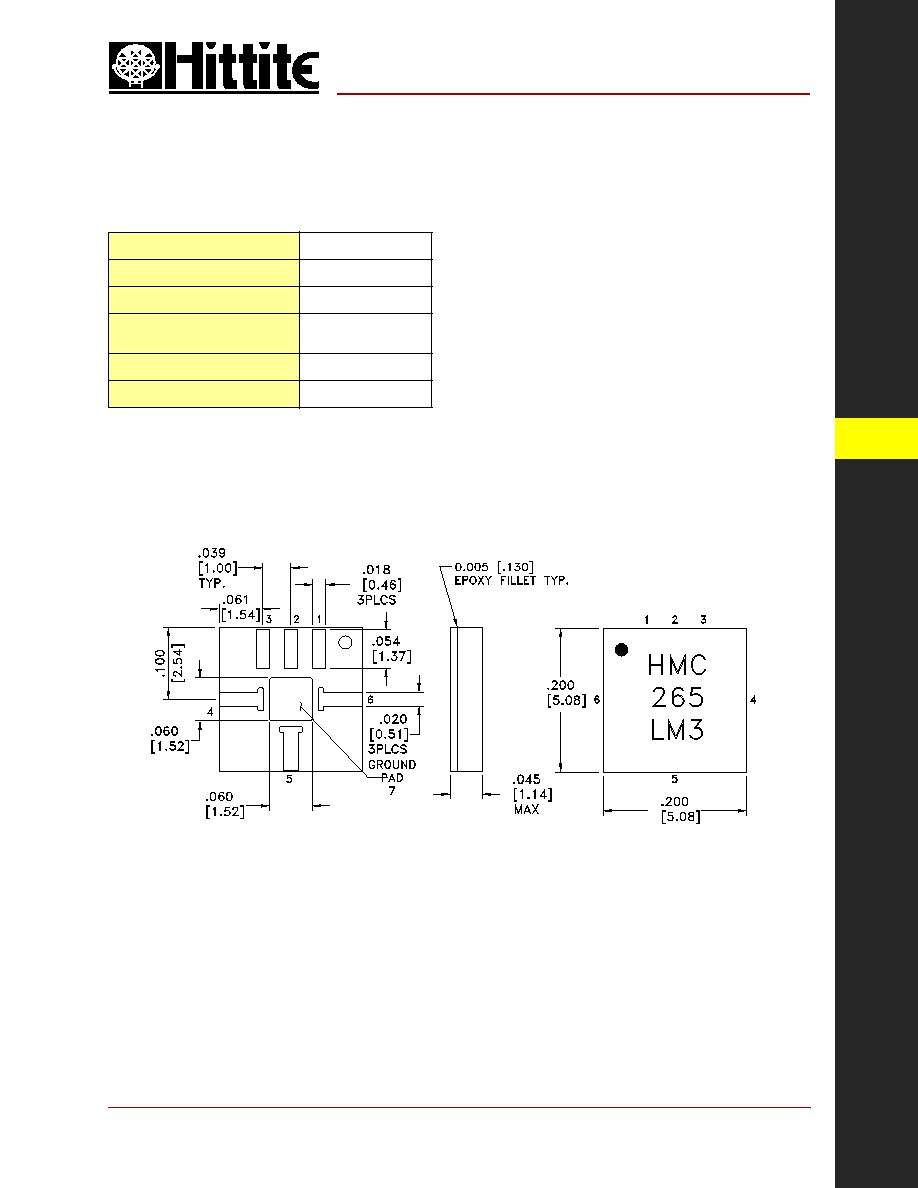
HMC265LM3
Outline Drawing
Absolute Maximum Ratings
RF / IF Input (Vdd = +5V)
+13 dBm
LO Drive (Vdd = +5V)
+13 dBm
Vdd
5.5V
Continuous Pdiss (Ta = 85 ∞C)
(derate 2.52 mW/∞C above 85 ∞C)
227 mW
Storage Temperature
-65 to +150 ∞C
Operating Temperature
-40 to +85 ∞C
NOTES:
1. MATERIAL: PLASTIC
2. PLATING: GOLD OVER NICKEL
3. DIMENSIONS ARE IN INCHES [MILLIMETERS].
4. ALL TOLERANCES ARE ± 0.005 [± 0.13].
5. ALL GROUNDS MUST BE SOLDERED TO PCB RF GROUND.
6.
∑
INDICATES PIN 1

MICROWAVE CORPORATION
12 - 98
For price, delivery, and to place orders, please contact Hittite Microwave Corporation:
12 Elizabeth Drive, Chelmsford, MA 01824 Phone: 978-250-3343 Fax: 978-250-3373
Order Online at www.hittite.com
MIXERS - SMT
12
Pin Number
Function
Description
Interface Schematic
1, 2
N/C
This pin may be connected to the housing ground or left
unconnected.
3
Vdd
Power supply for the LO Amplifi er. An external RF bypass
capacitor of 100 - 330 pF is required as close to the package as
possible.
4
RF
RF Port. This pin is AC coupled and matched to 50 Ohm from
20 - 30 GHz.
5
IF
IF Port. This pin is AC coupled and matched to 50 Ohm from
0.7 - 3 GHz.
6
LO
LO Port. This pin is AC coupled and matched to 50 Ohm from
10 - 15 GHz.
7
GND
Must be soldered to PCB RF ground.
GaAs MMIC SUB-HARMONIC
SMT MIXER, 20 - 31 GHz
v01.1201
Pin Description
HMC265LM3