Untitled-1
MICROWAVE CORPORATION
10 - 60
For price, delivery, and to place orders, please contact Hittite Microwave Corporation:
12 Elizabeth Drive, Chelmsford, MA 01824 Phone: 978-250-3343 Fax: 978-250-3373
Order Online at www.hittite.com
FREQ.
DIVIDER & DETECT
ORS - SMT
10
HMC403S8G
HBT DIGITAL PHASE-FREQUENCY
DETECTOR, DC - 1.3 GHz
v00.0501
General Description
Features
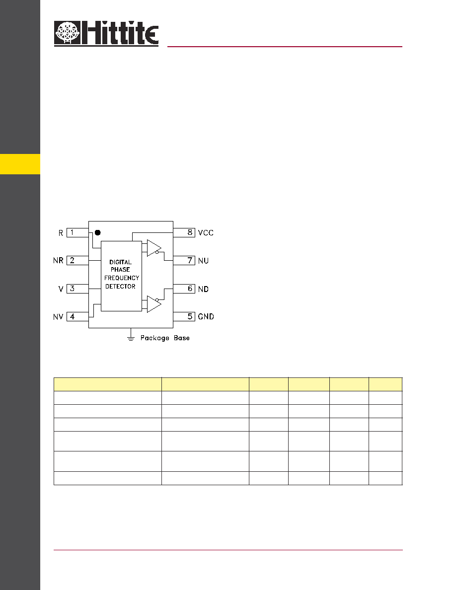
Functional Diagram
The HMC403S8G is a digital phase-frequency
detector intended for use in low noise phase-
locked loop applications. Its combination of high
frequency of operation along with its low phase
noise fl oor make possible synthesizers with wide
loop bandwidth and low N resulting in fast switch-
ing and very low phase noise. When used in
conjunction with a differential loop amplifi er, the
HMC403S8G generates an output voltage that
can be used to phase lock a VCO to a reference
oscillator. The device is available in a small out-
line 8-lead SOIC plastic package.
1.3 GHz Operation
Low SSB Phase Noise Floor:
-135 dBc/Hz at 100 KHz Offset
Differential Input/Single Ended Output
Output Buffer Amplifi ers
8-Lead SOIC SMT Package
Electrical Specifi cations,
T
A
= +25� C, Vcc = 5V
Typical Applications
This Phase Frequency Detector is a key
component in low phase noise frequency
synthesis applications such as:
�
VSAT
� Pt-Pt and Pt-MPt Radios
�
LMDS
�
Sonnet
1. Detector will operate down to DC for square-wave input signal.
Parameter
Conditions
Min.
Typ.
Max.
Units
Maximum Input Frequency
1.3
GHz
Minimum Input Frequency
Sine Wave Input [1]
0.1
GHz
Input Power Range
Fin = 0.1 to 1.3 GHz
-10
+10
dBm
Output Voltage
740
mV,
Pk - Pk
SSB Phase Noise
@ 100 kHz Offset
with 800 MHz Input
-135
dBc/Hz
Supply Current
86
mA
MICROWAVE CORPORATION
10 - 61
For price, delivery, and to place orders, please contact Hittite Microwave Corporation:
12 Elizabeth Drive, Chelmsford, MA 01824 Phone: 978-250-3343 Fax: 978-250-3373
Order Online at www.hittite.com
10
FREQ.
DIVIDERS & DETECT
ORS - SMT
-0.6
-0.4
-0.2
0
0.2
0.4
0.6
-
-/2
0
/2
250MHz
800MHz
1.3GHz
ERROR VOLTAGE (Vdc)
PHASE DIFFERENCE (rad)
-0.6
-0.4
-0.2
0
0.2
0.4
0.6
-
-/2
0
/2
+25 C
+85 C
-40 C
ERROR VOLTAGE (Vdc)
PHASE DIFFERENCE (rad)
GaAs MMIC SUB-HARMONICALLY PUMPED MIXER 17 - 25 GHz
HMC403S8G
HBT DIGITAL PHASE-FREQUENCY
DETECTOR, DC - 1.3 GHz
v00.0501
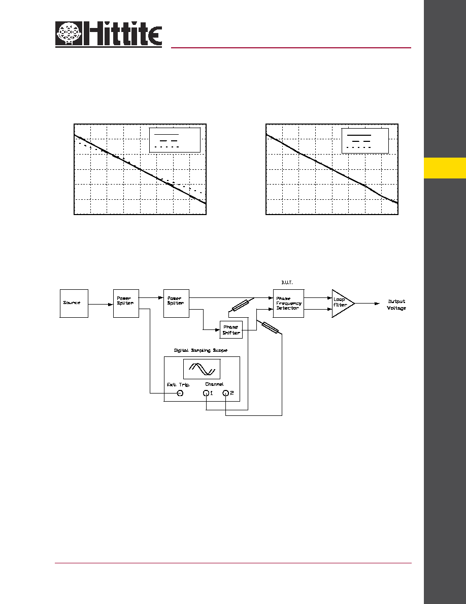
Error Voltage vs. Phase Difference,
Pin= 0 dBm, T= 25 �C *
Error Voltage vs. Phase Difference,
Pin= 0 dBm, Fin= 800 MHz *
Test Circuit:
* Error Voltage data taken using test circuit above. Loop fi lter gain has been subtracted from the result.
MICROWAVE CORPORATION
10 - 62
For price, delivery, and to place orders, please contact Hittite Microwave Corporation:
12 Elizabeth Drive, Chelmsford, MA 01824 Phone: 978-250-3343 Fax: 978-250-3373
Order Online at www.hittite.com
FREQ.
DIVIDER & DETECT
ORS - SMT
10
HBT DIGITAL PHASE-FREQUENCY
DETECTOR, DC - 1.3 GHz
v00.0501
HMC403S8G
-160
-150
-140
-130
-120
-110
-100
-90
-80
-70
-60
-50
-40
-30
-20
-10
0
10
2
10
3
10
4
10
5
10
6
250 MHz
800 MHz
1.3 GHz
SSB PHASE NOISE (dBc/Hz)
OFFSET FREQUENCY (Hz)
-160
-150
-140
-130
-120
-110
-100
-90
-80
-70
-60
-50
-40
-30
-20
-10
0
10
2
10
3
10
4
10
5
10
6
+25 C
+85 C
-40 C
SSB PHASE NOISE (dBc/Hz)
OFFSET FREQUENCY (Hz)
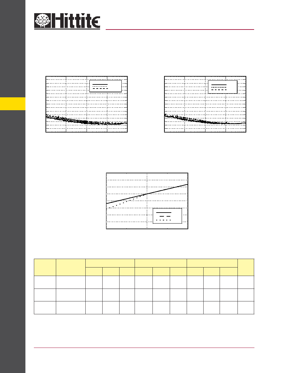
SSB Phase Noise Performance,
Pin= 0 dBm, Fin= 800 MHz
SSB Phase Noise Performance,
Pin= 0 dBm, T= 25 �C
60
65
70
75
80
85
90
95
100
4.75
5.00
5.25
+25 C
+85 C
-40 C
SUPPLY CURRENT (mA)
SUPPLY VOLTAGE (Vdc)
Supply Current vs. Supply Voltage
Typical DC Characteristics
Symbol
Characteristics
-40C
+25C
+85C
Unit
Min.
Typ.
Max.
Min.
Typ.
Max.
Min.
Typ.
Max.
Icc
Power Supply
Current
75
85
92
79
86
92
79
86
92
mA
Voh
Output High
Voltage
1.652
1.867
2.086
1.761
1.981
2.214
1.955
2.19
2.411
V
Vol
Output Low
Voltage
1.012
1.107
1.286
1.081
1.241
1.414
1.275
1.45
1.631
V
MICROWAVE CORPORATION
10 - 63
For price, delivery, and to place orders, please contact Hittite Microwave Corporation:
12 Elizabeth Drive, Chelmsford, MA 01824 Phone: 978-250-3343 Fax: 978-250-3373
Order Online at www.hittite.com
10
FREQ.
DIVIDERS & DETECT
ORS - SMT
HBT DIGITAL PHASE-FREQUENCY
DETECTOR, DC - 1.3 GHz
v00.0501
HMC403S8G
Absolute Maximum Ratings
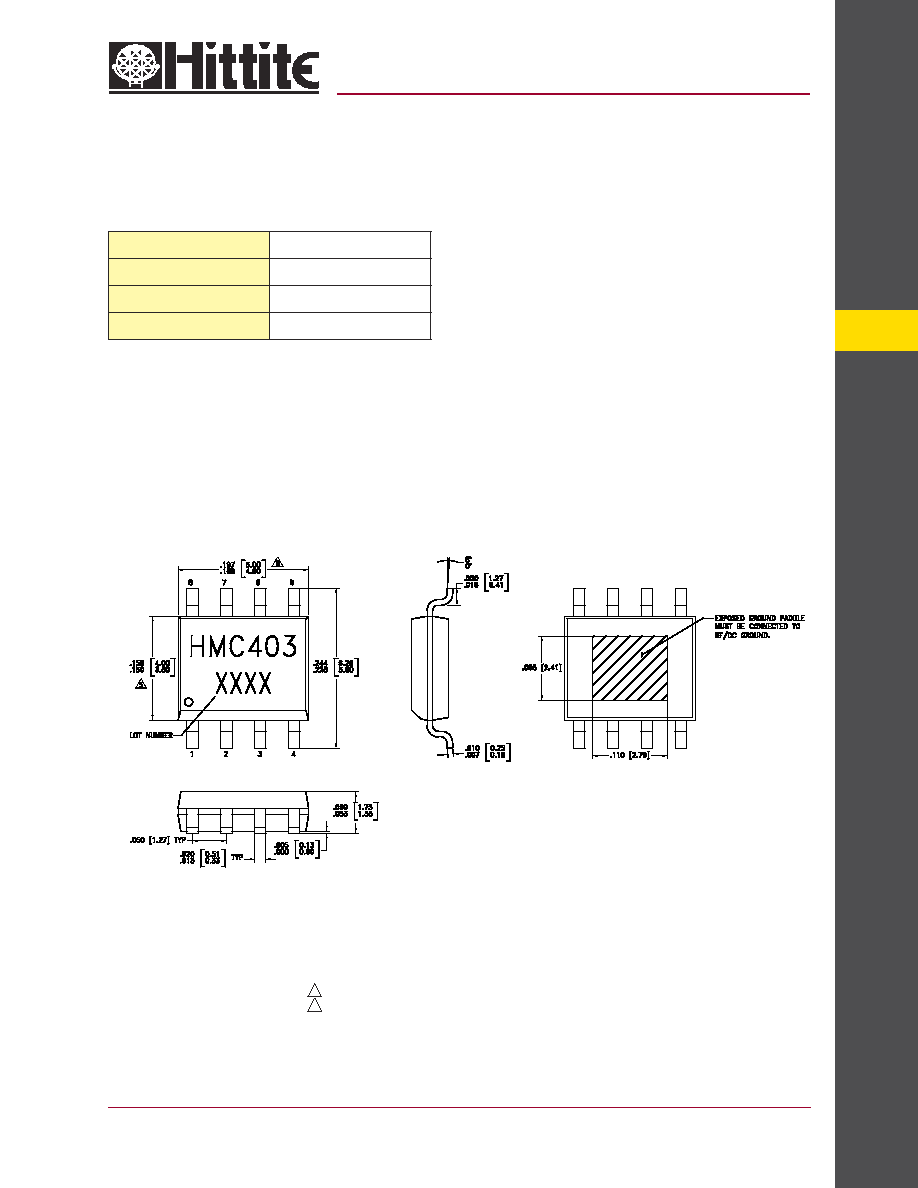
Outline Drawing
RF Input (Vcc = +5V)
+13 dBm
Vcc
+5.5V
Storage Temperature
-65 to +150 �C
Operating Temperature
-40 to +85 �C
NOTES:
1. PACKAGE BODY MATERIAL: LOW STRESS INJECTION MOLDED
PLASTIC SILICA AND SILICON IMPREGNATED.
2. LEADFRAME MATERIAL: COPPER ALLOY
3. LEADFRAME PLATING: Sn/Pb SOLDER
4. DIMENSIONS ARE IN INCHES [MILLIMETERS].
5. DIMENSION DOES NOT INCLUDE MOLDFLASH OF 0.15mm PER SIDE.
6. DIMENSION DOES NOT INCLUDE MOLDFLASH OF 0.25mm PER SIDE.
7. ALL GROUND LEADS AND GROUND PADDLE MUST BE SOLDERED
TO PCB RF GROUND.
MICROWAVE CORPORATION
10 - 64
For price, delivery, and to place orders, please contact Hittite Microwave Corporation:
12 Elizabeth Drive, Chelmsford, MA 01824 Phone: 978-250-3343 Fax: 978-250-3373
Order Online at www.hittite.com
FREQ.
DIVIDER & DETECT
ORS - SMT
10
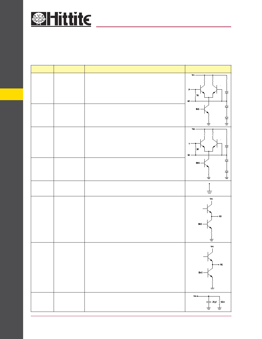
Pin Number
Function
Description
Interface Schematic
1
R
Reference input.
2
NR
Reference input complement.
3
V
VCO input.
4
NV
VCO input complement.
5
GND
Ground: Backside of package has exposed metal ground slug which
must be connected to ground.
6
ND
Down output complement
7
NU
Up output complement.
8
Vcc
Supply Voltage.
HBT DIGITAL PHASE-FREQUENCY
DETECTOR, DC - 1.3 GHz
v00.0501
HMC403S8G
Pin Description