
A
M
P
L
I
F
I
E
R
S
- C
O
NN
E
C
T
O
R
I
Z
E
D MOD
U
L
E
S
9
9 - 62
For price, delivery, and to place orders, please contact Hittite Microwave Corporation:
20 Alpha Road, Chelmsford, MA 01824 Phone: 978-250-3343 Fax: 978-250-3373
Order On-line at www.hittite.com
HMC-C024
WIDEBAND DRIVER AMPLIFIER
MODULE, 10 MHz - 20 GHz
v00.1005
General Description
Features
Functional Diagram
The HMC-C024 is a GaAs MMIC PHEMT Distributed
Driver Amplifi er in a miniature, hermetic module with
replaceable SMA connectors which operates bet-
ween 10 MHz and 20 GHz. The amplifi er provides
15 dB of gain, 3 to 4 dB noise fi gure and +24 dBm of
saturated output power. Deviation from linear phase
of only �2 degrees from 0.01 to 10 GHz make the
HMC-C024 ideal for OC192 fi
ber optic LN/MZ
modulator driver applications. The wideband amplifi er
I/Os are in-ternally matched to 50 Ohms and are
internally DC blocked. Integrated voltage regulators
allow for fl exible biasing of both the negative and
positive supply pins, while internal bias sequencing
circuitry assures robust operation.
Gain: 15 dB
Saturated Output Power: +24 dBm
Spurious-Free Operation
Regulated Supply and Bias Sequencing
Hermetically Sealed Module
Field Replaceable SMA connectors
-55 to +85�C Operating Temperature
Typical Applications
The HMC-C024 Wideband Driver is ideal for:
� OC192 LN/MZ Modulator Driver
� Telecom Infrastructure
� Microwave Radio & VSAT
� Military & Space
� Test Instrumentation
Electrical Specifications,
T
A
= +25� C, +VDC = +11V to +16V, -Vdc = -3V to -12V
Parameter
Min.
Typ.
Max.
Min.
Typ.
Max.
Min.
Typ.
Max.
Units
Frequency Range
0.010 - 6.0
6.0 - 12.0
12.0 - 20.0
GHz
Gain
14
16
13
15
10
13
dB
Gain Flatness
�0.75
�0.75
�1.0
dB
Gain Variation Over Temperature
0.018
0.025
0.018
0.025
0.018
0.025
dB/ �C
Noise Figure
3.5
3
4
dB
Input Return Loss
19
17
10
dB
Output Return Loss
14
14
12
dB
Output Power for 1 dB Compression (P1dB)
20
24
19
23
17
20
dBm
Saturated Output Power (Psat)
26
25
22
dBm
Output Third Order Intercept (IP3)
33
30
25
dBm
Saturated Output Voltage
10
10
8
Vpk-pk
Group Delay
�3
�3
�3
ps
Positive Supply Current (+IDC)
225
225
225
mA
Negative Supply Current (-IDC)
1.6
1.6
1.6
mA
A
M
P
L
I
F
I
E
R
S
- C
O
NN
E
C
T
O
R
I
Z
E
D MOD
U
L
E
S
9
9 - 63
For price, delivery, and to place orders, please contact Hittite Microwave Corporation:
20 Alpha Road, Chelmsford, MA 01824 Phone: 978-250-3343 Fax: 978-250-3373
Order On-line at www.hittite.com
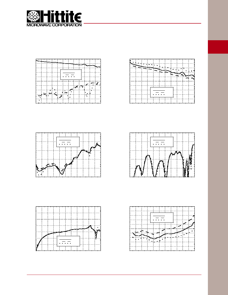
Noise Figure vs. Temperature
Gain vs. Temperature
Output Return Loss vs. Temperature
Gain & Return Loss
Reverse Isolation vs. Temperature
Input Return Loss vs. Temperature
-30
-25
-20
-15
-10
-5
0
5
10
15
20
0
2
4
6
8
10
12
14
16
18
20
22
24
S21
S11
S22
RESPONSE (dB)
FREQUENCY (GHz)
HMC-C024
WIDEBAND DRIVER AMPLIFIER
MODULE, 10 MHz - 20 GHz
v00.1005
-25
-20
-15
-10
-5
0
0
2
4
6
8
10
12
14
16
18
20
22
+25 C
+85 C
-55 C
RETURN LOSS (dB)
FREQUENCY (GHz)
0
1
2
3
4
5
6
7
8
9
10
0
2
4
6
8
10
12
14
16
18
20
22
+25 C
+85 C
-55 C
NOI
SE FI
GURE (dB)
FREQUENCY (GHz)
-70
-60
-50
-40
-30
-20
-10
0
0
2
4
6
8
10
12
14
16
18
20
22
+25 C
+85 C
-55 C
ISOLATION (dB)
FREQUENCY (GHz)
-25
-20
-15
-10
-5
0
0
2
4
6
8
10
12
14
16
18
20
22
+25 C
+85 C
-55 C
RETURN LOSS (dB)
FREQUENCY (GHz)
0
2
4
6
8
10
12
14
16
18
20
0
2
4
6
8
10
12
14
16
18
20
22
+25 C
+85 C
-55 C
GAIN
(dB)
FREQUENCY (GHz)

A
M
P
L
I
F
I
E
R
S
- C
O
NN
E
C
T
O
R
I
Z
E
D MOD
U
L
E
S
9
9 - 64
For price, delivery, and to place orders, please contact Hittite Microwave Corporation:
20 Alpha Road, Chelmsford, MA 01824 Phone: 978-250-3343 Fax: 978-250-3373
Order On-line at www.hittite.com
P1dB vs. Temperature
Psat vs. Temperature
Output IP3 vs. Temperature
-40
-35
-30
-25
-20
-15
-10
-5
0
5
10
15
20
25
0.001
0.01
0.1
1
10
S21
S11
S22
RESPONSE (dB)
FREQUENCY (GHz)
Group Delay
Deviation from Linear Phase
Low Frequency Gain and Return Loss
-200
-180
-160
-140
-120
-100
-80
-60
-40
-20
0
0
1
2
3
4
5
6
7
8
9
10
GROUP DELAY (ps)
FREQUENCY (GHz)
-5
-4
-3
-2
-1
0
1
2
3
4
5
0
1
2
3
4
5
6
7
8
9
10
DEVIATION FROM LINEAR PHASE (deg)
FREQUENCY (GHz)
20
22
24
26
28
30
32
34
36
38
40
0
2
4
6
8
10
12
14
16
18
20
22
+25 C
+85 C
-55 C
OIP3 (dBm)
FREQUENCY (GHz)
10
12
14
16
18
20
22
24
26
28
0
2
4
6
8
10
12
14
16
18
20
22
+25 C
+85 C
-55 C
Psat (dBm)
FREQUENCY (GHz)
10
12
14
16
18
20
22
24
26
28
0
2
4
6
8
10
12
14
16
18
20
22
+25 C
+85 C
-55 C
P1dB (dBm)
FREQUENCY (GHz)
HMC-C024
WIDEBAND DRIVER AMPLIFIER
MODULE, 10 MHz - 20 GHz
v00.1005

A
M
P
L
I
F
I
E
R
S
- C
O
NN
E
C
T
O
R
I
Z
E
D MOD
U
L
E
S
9
9 - 65
For price, delivery, and to place orders, please contact Hittite Microwave Corporation:
20 Alpha Road, Chelmsford, MA 01824 Phone: 978-250-3343 Fax: 978-250-3373
Order On-line at www.hittite.com
Absolute Maximum Ratings
Positive Bias Supply Voltage (+VDC)
+17V Max
Negative Bias Supply (-VDC)
-16V Min.
RF Input Power (RFin)
+23 dBm
Storage Temperature
-65 to +150 �C
Operating Temperature
-55 to +85 �C
Input OC-192 Eye Diagram
[1][2]
Output OC-192 Eye Diagram
[1][3]
[1] Test Conditions:
Pattern generated with an Agilent N4901B Serial BERT
Eye diagram data presented on an infi niium DCA 86100A.
Rate = 10.709 GB/s
Pseudo Random Code = 2
23
-1
[2] Vertical Scale = 200 mV/Div.
[3] Vertical Scale = 1 V/Div.
HMC-C024
WIDEBAND DRIVER AMPLIFIER
MODULE, 10 MHz - 20 GHz
v00.1005
ELECTROSTATIC SENSITIVE DEVICE
OBSERVE HANDLING PRECAUTIONS

A
M
P
L
I
F
I
E
R
S
- C
O
NN
E
C
T
O
R
I
Z
E
D MOD
U
L
E
S
9
9 - 66
For price, delivery, and to place orders, please contact Hittite Microwave Corporation:
20 Alpha Road, Chelmsford, MA 01824 Phone: 978-250-3343 Fax: 978-250-3373
Order On-line at www.hittite.com
HMC-C024
WIDEBAND DRIVER AMPLIFIER
MODULE, 10 MHz - 20 GHz
v00.1005
Pin Number
Function
Description
Interface Schematic
1
RFIN &
RF Ground
RF input connector, SMA female, fi eld replaceable.
This pin is AC coupled and matched to 50 Ohms
from 0.01 - 20.0 GHz.
2
+VDC
Positive power supply voltage for the amplifi er.
3
RFOUT &
RF Ground
RF output connector, SMA female. This pin is AC coupled
and matched to 50 Ohms from 0.01 - 20.0 GHz.
4
-VDC
Negative power supply votage for the amplifi er
5
GND
Power supply ground.
Pin Descriptions