HT85XXX
Green Voice
TM
Selection Table
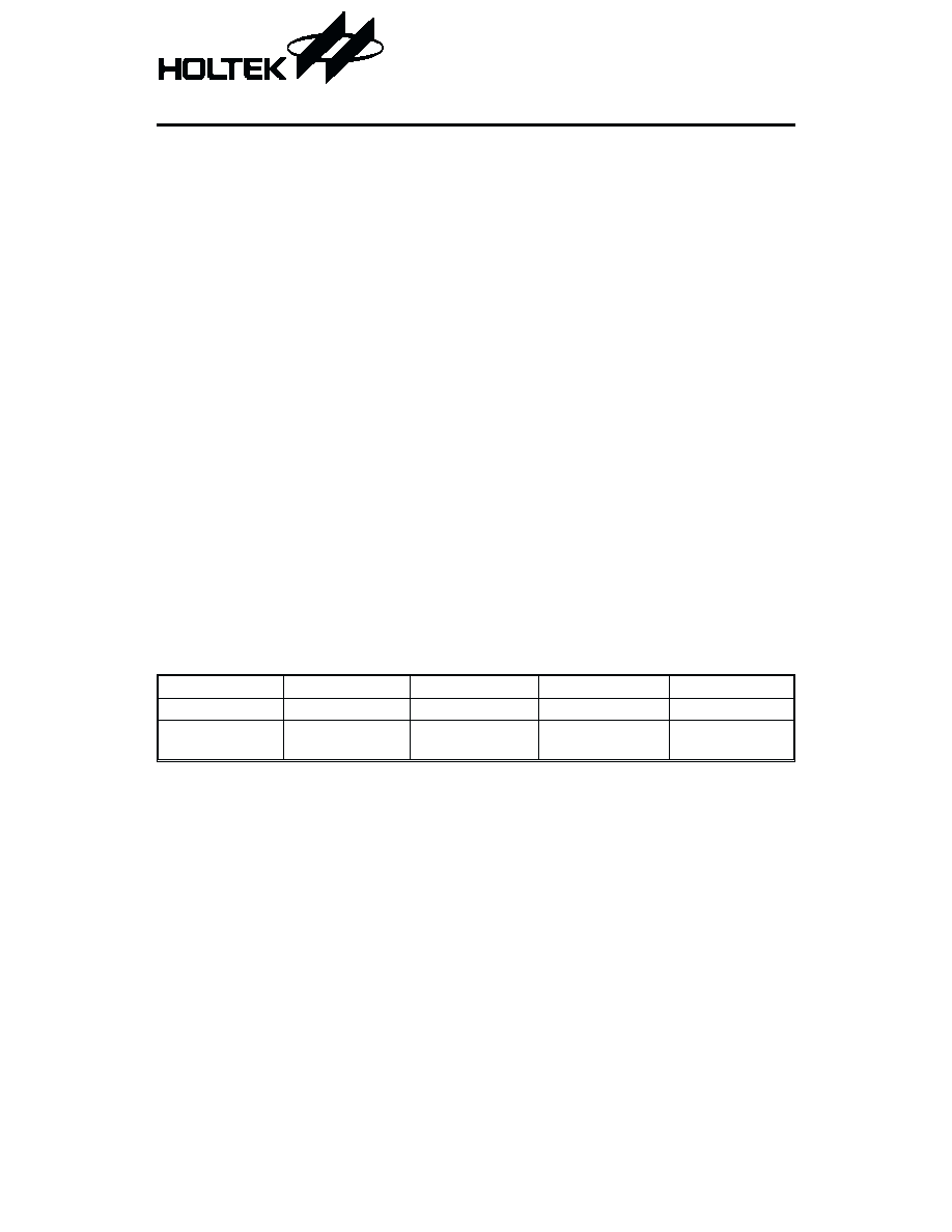
The HT85XXX series provides various voice capacity as shown below:
Part No.
HT85036
HT85048
HT85072
HT85096
ROM
768Kb
1024Kb
1536Kb
2048Kb
Voice
Length
36 sec
48 sec
72 sec
96 sec
Note: The voice capacity is based on a sampling rate of 4-bit ADPCM 5.25kHz.
*: under development.
1
August 24, 2000
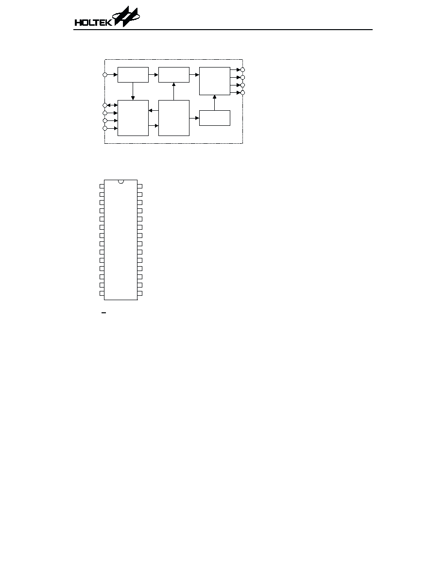
General Description
The HT85XXX family is a series of programma-
ble speech synthesizers and tone generators de-
signed for user-defined voice and melody
applications. It provides various sampling
rates and beats, tone levels, tempos for the
speech synthesizer and melody generator.
The HT85XXX series has a built-in high quality,
currenttypeD/Aoutputswith16levelsofvolume
control. The user¢s commands enable the user to
program the powerful custom function such as to
build-in a tiny controller. The Green Voice pro-
vides various operational functions similar to
arithmetic operation, logic operation, branch de-
cision, random counter, and a programmable
timer. The Green Voice series are suitable for
versatilevoiceandsoundeffect applications.
The HT85XXX Green Voice series is Easy For-
mat
TM
supported.
Features
∑
Operating voltage: 2.4V~5.0V
∑
Driver speaker (32W) V
DD
=4.5V,
I
DD
=90mA
∑
Programmable tone melody generator
∑
ADPCM, m-law PCM, PCM synthesis
∑
Wide range of sampling rate for voice
synthesis
∑
Minimum sampling rate step: 100Hz
∑
Voice melody mixed output
∑
Programmable 2 channels of melody
mixed output
∑
Programmable 2 channels of voice
mixed output
∑
13 kinds of melody beats
∑
5 octaves of tone level and 18 tempos
∑
16 levels of digital volume control
∑
Eight programmable I/O pins
∑
Four programmable input pins
∑
Provides 36 sec to 96 sec of voice capacity
∑
Timer controller
∑
Voice fill-in function
∑
Powerful user-defined functions
∑
Power-on initial setting
∑
28-pin SKDIP package
Green Voice
TM
and Easy Format
TM
are trademark of Grow With Me, Inc
.

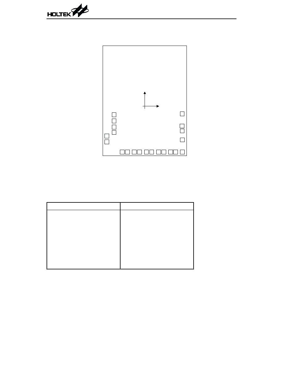
Pin Description
Pin No. Pin Name I/O
Internal
Connection
Description
1, 2, 8,
24~28
NC
æ
æ
No connection
3, 4, 5
PP0, PDA,
PP1
O
æ
Green Voice Speaker control pin
6
VDD
æ
æ
Positive power supply
7
AUD
O
PMOS
Open Drain Audio output for driving an external transistor
15~9
PB1~PB7
I/O
Pull-high
or CMOS
Bidirectional I/O pins
Can be optioned as trigger inputs or LED outputs
16
PB0
I/O
Pull-high
or CMOS
Bidirectional I/O pins
Can be optioned as CDS interface with internal
Schmitt trigger input
20~17
PA0~PA3
I
Wake-up
Pull-high
Trigger inputs
Can also be configured as wake-up inputs
21, 22
VSS
æ
æ
Negative power supply, ground
23
OSC
I
æ
Built-in RC oscillator
An oscillator resistor is connected between OSC and VSS
Absolute Maximum Ratings
Supply Voltage.................................-0.3V to 6V
Storage Temperature.................-50∞C to 125∞C
Input Voltage.................V
SS
-0.3V to V
DD
+0.3V
Operating Temperature ..............-20∞C to 70∞C
Note: These are stress ratings only. Stresses exceeding the range specified under ≤Absolute Maxi-
mum Ratings≤ may cause substantial damage to the device. Functional operation of this device
at other conditions beyond those listed in the specification is not implied and prolonged expo-
sure to extreme conditions may affect device reliability.
Electrical Characteristics
Ta=25∞C
Symbol
Parameter
Test Conditions
Min. Typ. Max. Unit
V
DD
Conditions
V
DD
Operating Voltage
æ
æ
2.4
æ
5.2
V
I
STB
Standby Current
3V No load, system HALT
æ
1
3
mA
I
DD
Operating Current
3V No load, f
SYS
=4MHz
æ
5
8
mA
I
OL
PB0~PB7 Sink Current
3V V
OL
=0.3V
4
6
æ
mA
I
O
Max. AUD Output Current
3V V
OH
=0.6V
-1.5
-2
æ
mA
f
SYS
System Frequency
3V R
OSC
=240kW
3.6
4.0
4.4
MHz
HT85XXX
4
August 24, 2000

HT85XXX
5
August 24, 2000
Functional Description
The Green Voice series is a series of program-
mable speech synthesizers and melody genera-
tors. It provides various sampling rates and
beats, tone levels, tempos for speech synthe-
sizer and melody generator. For voice synthe-
sizer, the Green Voice provides 8-bit PCM, 6-bit
m-law PCM and 4-bit ADPCM synthesis. In
HT85XXX series, a mixed output of two chan-
nels PCM synthesis is allowed but only one
channel ADPCM synthesis is allowed. For mel-
ody generator, the Green Voice supports a tone
melody and PCM melody generator and two
channels mixed output for the whole series.
The Green Voice series build-in 8 programma-
ble I/O pins and 4 programmable input pins
along with powerful user¢s command. The
user¢s instructions are employed to develop
new and customized functions for a wide vari-
ety of innovative applications.
Speech and melody analysis
The speech and melody sources of the Green
Voice can be recorded and edited from the PC
sound card and media tools. Holtek¢s CAD tools
first load a speech source file as .WAV or .PCM
format, then transfer the speech file as PCM,
LOG-PCM or ADPCM format, and finally save
it to the internal mask ROM by changing a
layer of the mask. The PCM format generates a
higher sound quality whereas the ADPCM for-
mat brings about a longer recording capacity.
The melody source can either be in the .MID or
in the .MLD format.
The .MID file is the standard format of the win-
dows media tools. The .MLD file is a text for-
mat. After the .MID file is compiled, the .MLD
file is automatically generated.
The Green Voice can support the following com-
pression format of the voice .WAV and .PCM
file: AD4, PCM8, m-law PCM.
Current type D/A output
The HT85XXX series supply high accuracy cur-
rent type D/A output pins for audio output. The
output volume is changeable from 0 to 15 digi-
tal levels by writing a value to the VOLUME
registers. The D/A pins are PMOS open drain
structure and ouput synthesized signals for
driving a speaker through an external NPN
transistor when the chip is active. However, it
becomes floating when the chip is in the
standby state. An 8050 type transistor with
h
FE
=150 is recommended for the output driver
of the D/A output pin.
Melody/Tone generator
The HT85XXX family has a built-in mel-
ody/tone generator. The generator can generate
13 different kinds of melody beats, 5 octaves of
tone level, 18 tempos, and 2 channels mixed
output. Of these components, the melody tempo
is changeable and generates sound effects by
writing a control value to the TEMPO register.
The chip provides the following 18 tempos, 13
beats, and 5 octaves for user¢s programming.
∑
18 tempos (Beats/Min.)
68
78
82
93
100
105
109
114
119
125
132
139
147
156
179
192
227
310
∑
13 beats
1
24
1
12
1
8
1
6
1
4
1
3
1
2
2
3
3
4
1 4
3
3
2
2
,
, , , , , , , ,
,
, ,
∑
5 octaves
C1~B1, C2~B2, C3~B3, C4~B4, C5~B5