 | –≠–Ľ–Ķ–ļ—ā—Ä–ĺ–Ĺ–Ĺ—č–Ļ –ļ–ĺ–ľ–Ņ–ĺ–Ĺ–Ķ–Ĺ—ā: HI-318X | –°–ļ–į—á–į—ā—Ć:  PDF PDF  ZIP ZIP |
HI-3182, HI-3183, HI-3184, HI-3185
HI-3186, HI-3187, HI-3188
The HI-3182, HI-3183, HI-3184, HI-3185, HI-3186, HI-3187 and
HI-3188 bus interface products are silicon gate CMOS devices
designed as a line driver in accordance with the ARINC 429 bus
specifications. In addition to being functional upgrades of Holt's
HI-8382 & HI-8383 products, they are also alternate sources for
the HS-3182 ( Intersil/Harris), the RM3182 (Fairchild /Raytheon)
and a variety of similar line driver products from other manufac-
turers.
Inputs are provided for clocking and synchronization. These
signals are AND'd with the DATA inputs to enhance system
performance and allow the HI-318X series of products to be
used in a variety of applications. Both logic and synchronization
inputs feature built-in 2,000V minimum ESD input protection as
well as TTL and CMOS compatibility.
The differential outputs of the HI-318X series of products are
programmable to either the high speed or low speed ARINC 429
output rise and fall time specifications through the use of two
external capacitors. The output voltage swing is also adjustable
by the application of an external voltage to the VREF input.
Products with 0, 13 or 37.5 ohm resistors in series with each
ARINC output are available. In addition, the
fuse in series with each
output.
The HI-318X series of line drivers are intended for use where
logic signals must be converted to ARINC 429 levels such as
when using an ASIC, the HI-3282/HI-8282A ARINC 429 Serial
Transmitter/Dual Receiver, the HI-6010 ARINC 429 Transmit-
ter/Receiver or the HI-8783 ARINC Interface Device.
Holt
products are readily available for both industrial and military
applications. Please contact the Holt Sales Department for
additional information.
HI-3182, HI-3184
and HI-3187 products also have a
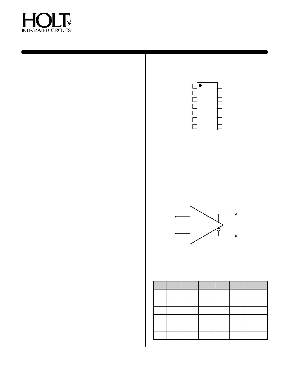
PIN CONFIGURATION
(Top View)
GENERAL DESCRIPTION
!
!
!
!
!
!
Low power CMOS
TTL and CMOS compatible inputs
Programmable output voltage swing
Plastic 14 & 16-pin thermally enhanced SOIC
packages available
Pin-for-Pin alternative for Intersil/Fairchild
applications
Operates at data rates up to 100 Kbits
Overvoltage protection
Industrial and Military temperature ranges
!
!
!
Adjustable ARINC rise and fall times
FEATURES
HI-3184PS, HI-3185PS, HI-3186PS
& HI-3187PS
14 - PIN PLASTIC SMALL OUTLINE (ESOIC)
NB
**
FUNCTION
ARINC 429 DIFFERENTIAL LINE DRIVER
_
+
TRUTH TABLE
SYNC CLOCK DATA(A) DATA(B) AOUT
BOUT COMMENTS
X
L
X
X
0V
0V
NULL
L
X
X
X
0V
0V
NULL
H
H
L
L
0V
0V
NULL
H
H
L
H
-V
+V
LOW
H
H
H
L
+V
-V
HIGH
H
H
H
H
0V
0V
NULL
REF
REF
REF
REF
February 2003
ARINC 429 DIFFERENTIAL LINE DRIVER
14 V
13 CLOCK
12 DATA (B)
11 C
10 B
9
+V
8
GND
1
B
OUT
V
1
GND (See Note * )
2
SYNC
3
DATA (A)
4
C
5
A
6
-V
7
REF
A
OUT
(See Page 6 for additional package pin configurations)
Notes: * Pin 2 may be left floating
** Thermally Enhanced SOIC Package
(DS3182 Rev. D )
02/03
HOLT INTEGRATED CIRCUITS
www.holtic.com

FUNCTIONAL DESCRIPTION
The SYNC and CLOCK inputs establish data synchronization
utilizing two AND gates, one for each data input (figure 2).
Each logic input, including the power enable (
) input,
are TTL/CMOS compatible.
Figure 1 illustrates a typical ARINC 429 bus application.
Three power supplies are necessary to operate the HI-3182;
typically +15V, -15V and +5V. The chip also works with Ī12V
supplies. The +5V supply can also provide a reference
voltage that determines the output voltage swing.
The
differential output voltage swing will equal 2V
. If a value of
V
other than +5V is needed, a separate +5V power supply
is required for pin V .
With the DATA (A) input at a logic high and DATA (B) input at a
logic low, A
will switch to the +V
rail and B
will
switch to the -V
rail (ARINC HIGH state). With both data
input signals at a logic low state, the outputs will both switch to
0V (ARINC NULL state).
The driver output impedance, R
, is nominally 75, 26 or 0
ohms depending on the option chosen. The rise and fall times
of the outputs can be calibrated through the selection of two
external capacitor values th
re connected to the C and C
input pins. Typical values for high-speed operation
(100KBPS) are C = C = 75pF and for low-speed operation
(12.5 to 14KBPS) C = C = 500pF.
STROBE
REF
REF
OUT
REF
OUT
REF
OUT
1
A
B
A
B
A
B
at a
The C and C pins swing between +5V and ground allowing
the switching of capacitor values with an external single-
supply analog switch.
A
B
The ARINC outputs can be put in a tri-state mode by applying
a logic high to the
input pin. If this feature is not
being used, the pin should be tied to ground. The
STROBE
STROBE
function is not available in the 14 & 16-pin SOIC package
configurations where the pin is internally connected to
ground.
The ARINC outputs of the HI-3182, HI-3184 and HI-3187 are
protected by internal fuses capable of sinking between 800 -
900 mA for short periods of time (125 s).
The Vref pin has an internal pull-up resistor to V+, allowing the
use of a simple external zener diode to set the reference
voltage.
m
POWER SUPPLY SEQUENCING
The power supplies should be controlled to prevent large
currents during supply turn-on and turn-off. The
recommended sequence is +V followed by V , always
ensuring that +V is the most positive supply. The -V supply
is not critical and can be asserted at any time.
1
HI-3182, HI-3183, HI-3184, HI-3185, HI-3186, HI-3187, HI-3188
DATA (A)
OUT
DATA (B)
INPUTS
TO ARINC BUS
A
OUT
B
REF
V
1
V
SYNC
CLOCK
-V
+V
STROBE
GND
B
A
C
C
-15V
+15V
+5V
Figure 1.
ARINC 429 BUS APPLICATION
Figure 2.
FUNCTIONAL BLOCK DIAGRAM
OUT
B
Shorted on
HI-3186, HI-3187, HI-3188
C
L
REF
F
A
R
L
F
B
OUT
A
OUTPUT
DRIVER (B)
OUTPUT
DRIVER (A)
B
C
GND
-V
DATA (A)
DATA (B)
SYNC
CLOCK
V
1
STROBE
A
C
V
+V
LEVEL SHIFTER
AND SLOPE
CONTROL (B)
LEVEL SHIFTER
AND SLOPE
CONTROL (A)
CURRENT
REGULATOR
13
W
13
W
24.5
W
Shorted on
HI-3183, HI-3186
HI-3187, HI-3188
Shorted on
HI-3183, HI-3185
HI-3186, HI-3188
24.5
W
HOLT INTEGRATED CIRCUITS
2

SYMBOL
FUNCTION
DESCRIPTION
V
ANALOG
Ref. voltage used to determine output voltage swing. Pin sources current to allow use of a zener reference.
INPUT
A logic high tri-states the ARINC outputs. Not available in the 14-pin SOIC package (tied to GND internally).
SYNC
INPUT
Synchronizes data inputs
DATA (A)
INPUT
Data input terminal A
C
INPUT
Connection for DATA (A) slew-rate capacitor
A
OUTPUT
ARINC output terminal A
-V
POWER
-12V to -15V
GND
POWER
0.0V
+V
POWER
+12V to +15V
B
OUTPUT
B
C
INPUT
DATA (B)
INPUT
B
CLOCK
INPUT
Synchronizes data inputs
V
POWER
+5V Ī5%
REF
A
OUT
OUT
B
1
STROBE
ARINC output terminal
Connection for DATA (B) slew-rate capacitor
Data input terminal
PARAMETER
SYMBOL
CONDITIONS
OPERATING RANGE
MAXIMUM
UNIT
Differential Voltage
V
Voltage between +V and -V terminals
40
V
Supply Voltage
+V
+10.8 to +16.5
V
-V
-10.8 to -16.5
V
V
+5 Ī5%
+7
V
Voltage Reference
V
For ARINC 429
+5 Ī5%
6
V
For Applications other than ARINC
1.5 to 6
6
V
Input Voltage Range
V
GND -0.3
V
V1 +0.3
V
Output Short-Circuit Duration
See Note: 1
Output Overvoltage Protection
See Note: 2
Operating Temperature Range
T
High-temp & Military
-55 to +125
įC
Industrial
-40 to +85
įC
Storage Temperature Range
T
Ceramic & Plastic
-65 to +150
įC
Lead Temperature
Soldering, 10 seconds
+275
įC
Junction Temperature
T
+175
įC
Note 1. Heatsinking may be required for continuous Output Short Circuit at +125įC and for 100KBPS at +125įC.
Note 2. The fuses used for Output Overvoltage Protection may be blown by the presence of a voltage at either output that is greater
than Ī12.0V with respect to GND. (HI-3182, 3184 & 3187 only)
DIF
1
REF
IN
A
STG
J
>
<
ABSOLUTE MAXIMUM RATINGS
All Voltages referenced to GND, TA = Operating Temperature Range (unless otherwise specified)
PIN DESCRIPTIONS
NOTE: Stresses above those listed under "Absolute Maximum Ratings" may cause permanent damage to the device. These are stress ratings
only. Functional operation of the device at these or any other conditions above those indicated in the operational sections of the specifications
is not implied. Exposure to absolute maximum rating conditions for extended periods may affect device reliability.
HI-3182, HI-3183, HI-3184, HI-3185, HI-3186, HI-3187, HI-3188
HOLT INTEGRATED CIRCUITS
3
PARAMETER
SYMBOL
CONDITION
MIN
TYP
MAX UNITS
Supply Current +V (Operating)
(+V)
No Load
(0 - 100KBPS)
+16
mA
Supply Current -V (Operating)
(-V)
No Load
(0 - 100KBPS)
-16
mA
Supply Current
(Operating)
(
)
No Load
(0 - 100KBPS)
500
ĶA
Reference Pin Current
(Operating)
(
)
No Load,
REF = 5V (0 - 100KBPS)
-1.0
-0.63
-0.5
mA
Supply Current +V (During Short Circuit Test)
(+V)
Short to Ground
(See Note: 1)
150
mA
Supply Current -V (During Short Circuit Test)
(-V)
Short to Ground
(See Note: 1)
-150
mA
Output Short Circuit Current (Output High)
Short to Ground
=0 (See Note: 2)
-80
mA
Output Short Circuit Current (Output Low)
Short to Ground
=0 (See Note: 2)
+80
mA
Input Current (Input High)
1.0
ĶA
Input Current (Input Low)
-1.0
ĶA
Input Voltage High
2.0
V
Input Voltage Low
0.5
V
Output Voltage High (Output to Ground)
No Load
(0 -100KBPS)
+V
+V
V
-.
+.
Output Voltage Low (Output to Ground)
No Load
(0 -100KBPS)
-V
-V
V
-.
+.
Output Voltage Null
No Load
(0-100KBPS)
-250
+250
mV
Input Capacitance
15
pF
I
I
V
I
V
V
I
V
V
I
I
I
V
I
V
I
I
V
V
V
V
V
C
CCOP
CCOP
1
CCOP
1
REF
CCOP
REF
SC
SC
OHSC
MIN
OLSC
MIN
IH
IL
IH
IL
OH
25
25
OL
25
25
NULL
IN
See Note 1
REF
REF
REF
REF
Note 1. Not tested, but characterized at initial device design and after major process and/or design change which affects this parameter.
Note 2. Interchangeability of force and sense is acceptable.
DC ELECTRICAL CHARACTERISTICS
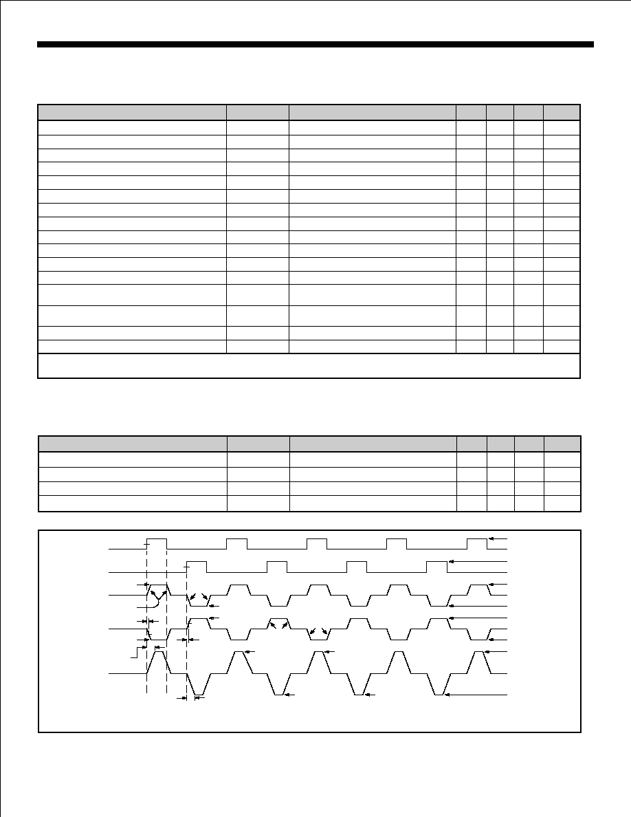
AC ELECTRICAL CHARACTERISTICS
+V = +15V, -V = -15V, V = V
= +5.0V, T
= Operating Temperature Range (unless otherwise specified).
1
REF
A
PARAMETER
SYMBOL
CONDITION
MIN
TYP
MAX UNITS
Rise Time (
,
)
=
= 75pF
See Figure 3.
1.0
2.0
Ķs
Fall Time (
,
)
=
= 75pF
See Figure 3.
1.0
2.0
Ķs
Propagtion Delay Input to Output
=
= 75pF
See Figure 3.
3.0
Ķs
Propagtion Delay Input to Output
=
= 75pF
See Figure 3.
3.0
Ķs
A
B
t
C
C
A
B
t
C
C
t
C
C
t
C
C
OUT
OUT
R
A
B
OUT
OUT
F
A
B
PLH
A
B
PHL
A
B
Figure 3. SWITCHING WAVEFORMS
-9.5V to -10.5V
+9.5V to +10.5V
-4.75V to -5.25V
2.0V
+4.75V to +5.25V
2.0V
0.5V
0.5V
-4.75V to -5.25V
+4.75V to +5.25V
DATA (A) 0V
DATA (B) 0V
A
OUT
0V
B
OUT
0V
DIFFERENTIAL
OUTPUT 0V
(
)
A
B
OUT -
OUT
50%
50%
V
REF
ADJUST
BY
C
A
t
PHL
ADJUST
BY
C
A
-V
REF
50%
50%
t
PLH
t
R
+V
REF
-V
REF
ADJUST
BY
C
B
ADJUST
BY
C
B
t
F
2V
REF
-2V
REF
HIGH
NULL
LOW
NOTE: OUTPUTS UNLOADED
+V = +15V, -V = -15V, V = V
= +5.0V, T
= Operating Temperature Range (unless otherwise specified).
1
REF
A
HI-3182, HI-3183, HI-3184, HI-3185, HI-3186, HI-3187, HI-3188
HOLT INTEGRATED CIRCUITS
4

Notes:
1. All data taken
on devices soldered to a single layer copper PCB (3" X 4.5" X .062").
2. At 100% duty cycle, 15V power supplies. For 12V power supplies multiply all tabulated values by 0.8.
3. High Speed: Data Rate = 100 Kbps, Load: R = 400 Ohms, C = 10 nF. Data not presented for C = 30 nF
as this is considered unrealistic for high speed operation.
4. Similar results would be obtained with A
shorted to B
.
5. For applications requiring survival with continuous short circuit, operation above Tj = 175įC is not recommended.
6. Data will vary depending on air flow and the method of heat sinking employed.
in still air
OUT
OUT
HI-318X PACKAGE THERMAL CHARACTERISTICS
JUNCTION TEMPERATURE, Tj
T
A = 25
o
C
T
A = 85
o
C
T
A=125
o
C
Unsoldered
82
57įC
117įC
157įC
Soldered
65
51įC
111įC
151įC
Unsoldered
51
45įC
105įC
145įC
Soldered
28
36įC
96įC
136įC
JUNCTION TEMPERATURE, Tj
T
A = 25
o
C
T
A = 85
o
C
T
A=125
o
C
Unsoldered
82
87įC
147įC
187įC
Soldered
65
78įC
138įC
178įC
Unsoldered
51
64įC
124įC
164įC
Soldered
28
53įC
113įC
153įC
PACKAGE STYLE
1
MAXIMUM ARINC LOAD
3, 6
A
OUT
and B
OUT
Shorted to Ground
3, 4, 5, 6
HEAT SINK
HEAT SINK
PACKAGE STYLE
1
SUPPLY CURRENT
2
20 mA
20 mA
ō
JA
(įC/W )
14-pin Thermally
Enhanced Plastic
SOIC (ESOIC)
20 mA
20 mA
ō
JA
(įC/W )
SUPPLY CURRENT
2
16-pin Thermally
Enhanced Plastic
SOIC (ESOIC)
14-pin Thermally
Enhanced Plastic
SOIC (ESOIC)
36 mA
36 mA
16-pin Thermally
Enhanced Plastic
SOIC (ESOIC)
40 mA
40 mA
HEAT SINK - ESOIC PACKAGES
Both the 14-pin and 16-pin thermally enhanced SOIC
packages are used for HI-318X products. These ESOIC
packages include a metal heat sink located on the bottom
surface of the device. This heat sink should be soldered
down to the printed circuit board for optimum thermal
dissipation. The heat sink is electrically isolated from the
chip and can be soldered to any ground or power plane.
However, since the chip's substrate is at +V, connecting
the heat sink to this power plane is recommended to avoid
coupling noise into the circuit.
HOLT INTEGRATED CIRCUITS
5
HI-3182, HI-3183, HI-3184, HI-3185, HI-3186, HI-3187, HI-3188

ADDITIONAL PIN CONFIGURATIONS
(See page 1 for 14-Pin Small Outline SOIC)
VREF
STROBE
SYNC
DATA(A)
CA
AOUT
-V
GND
+V
N/C
BOUT
CB
DATA(B)
CLOCK
V1
N/C
1
2
3
4
5
6
7
8
9
10
11
12
13
14
15
16
HI-3182CD
HI-3183CD
16 - PIN
CERAMIC
SIDE BRAZED
DIP
V
- 1
GND (See Note * ) - 2
SYNC - 3
DATA(A) - 4
C
- 5
A
- 6
-V - 7
GND - 8
REF
A
OUT
16 - V
15 - N/C
14 - CLOCK
13 - DATA(B)
12 - C
11 - B
10 - N/C
9 - +V
1
B
OUT
HI-3182PS, HI-3183PS, HI-3188PS
Notes:
** Thermally Enhanced SOIC package
* Pin 2 may be left floating
HI-3182, HI-3183, HI-3184, HI-3185, HI-3186, HI-3187, HI-3188
VREF
STROBE
SYNC
DATA(A)
CA
AOUT
-V
GND
+V
N/C
BOUT
CB
DATA(B)
CLOCK
V1
N/C
1
2
3
4
5
6
7
8
9
10
11
12
13
14
15
16
HI-3182CR
HI-3183CR
16 - PIN
CERDIP
5
6
7
8 9 10 11 12 13
30
31
32
1
2
3
4
20
19
18
17
16
15
14
N/C
N/C
+V
GND
N/C
-V
N/C
CLOCK
V
N/C
V
SYNC
N/C
1
REF
STROBE
N/C
N/C
N/C
N/C
DA
T
A(B)
C
N/C
N/C
B
B
OUT
N/C
N/C
N/C
DA
T
A(A)
C
N/C
N/C
N/C
A
A
OUT
HI-3182CJ
HI-3183CJ
29 28 27 26 25 24 23 22 21
32 - PIN CERQUAD
4
3
2
1 28 27 26
12 13 14 15 16 17 18
5
6
7
8
9
10
11
25
24
23
22
21
20
19
CLOCK
N/C
DATA (B)
C
N/C
N/C
N/C
B
N/C
DATA (A)
N/C
N/C
C
N/C
N/C
A
SYNC
N/C
V
V
N/C
N/C
STROBE
REF
1
N/C
A
-V
GND
+V
B
N/C
OUT
OUT
HI-3182CL
HI-3183CL
28 - PIN CERAMIC LCC
16 - PIN PLASTIC SMALL OUTLINE (ESOIC)**
CLOCK
N/C
DATA (B)
C
N/C
N/C
N/C
B
12 13 14 15 16 17 18
5
6
7
8
9
10
11
N/C
DATA (A)
N/C
N/C
C
N/C
N/C
A
HI-3182PJ
HI-3183PJ
4
3
2
1 28 27 26
SYNC
N/C
V
V
N/C
N/C
STROBE
REF
1
25
24
23
22
21
20
19
N/C
A
-V
GND
+V
B
N/C
OUT
OUT
28 - PIN PLASTIC PLCC
HOLT INTEGRATED CIRCUITS
6
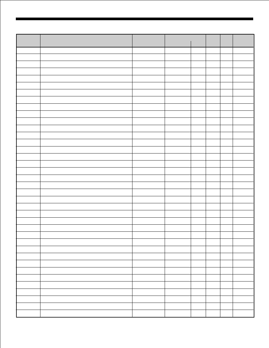
ORDERING INFORMATION
Legend:
NB
- Narrow Body
ESOIC - Thermally Enhanced Small Outline Package (SOIC w/built-in heat sink)
WB
- Wide Body
HI-3182, HI-3183, HI-3184, HI-3185, HI-3186, HI-3187, HI-3188
NUMBER
PACKAGE DESCRIPTION
RANGE
RESISTANCE FUSE
FLOW
IN
IN
FINISH
PART
TEMPERATURE
BURN
LEAD
OUTPUT SERIES
HI-3182CDI
16 PIN CERAMIC SIDE BRAZED DIP
-40įC T0 +85įC
37.5
YES
I
NO
GOLD
HI-3182CDT
16 PIN CERAMIC SIDE BRAZED DIP
-55įC T0 +125įC
37.5
YES
T
NO
GOLD
HI-3182CDM 16 PIN CERAMIC SIDE BRAZED DIP
-55įC T0 +125įC
37.5
YES
M
YES
SOLDER
HI-3182CJI
32 PIN J-LEAD CERQUAD
-40įC T0 +85įC
37.5
YES
I
NO
SOLDER
HI-3182CJT
32 PIN J-LEAD CERQUAD
-55įC T0 +125įC
37.5
YES
T
NO
SOLDER
HI-3182CLI
28 PIN CERAMIC LEADLESS CHIP CARRIER (LCC)
-40įC T0 +85įC
37.5
YES
I
NO
GOLD
HI-3182CLT
28 PIN CERAMIC LEADLESS CHIP CARRIER (LCC)
-55įC T0 +125įC
37.5
YES
T
NO
GOLD
HI-3182CLM
28 PIN CERAMIC LEADLESS CHIP CARRIER (LCC)
-55įC T0 +125įC
37.5
YES
M
YES
SOLDER
HI-3182CRI
32 PIN CERDIP
-40įC T0 +85įC
37.5
YES
I
NO
SOLDER
HI-3182CRT
32 PIN CERDIP
-55įC T0 +125įC
37.5
YES
T
NO
SOLDER
HI-3182PJI
28 PIN PLASTIC J-LEAD PLCC
-40įC T0 +85įC
37.5
YES
I
NO
SOLDER
HI-3182PJT
28 PIN PLASTIC J-LEAD PLCC
-55įC T0 +125įC
37.5
YES
T
NO
SOLDER
HI-3182PSI
16 PIN PLASTIC SMALL OUTLINE - WB (ESOIC)
-40įC T0 +85įC
37.5
YES
I
NO
SOLDER
HI-3182PST
16 PIN PLASTIC SMALL OUTLINE - WB (ESOIC)
-55įC T0 +125įC
37.5
YES
T
NO
SOLDER
HI-3183CDI
16 PIN CERAMIC SIDE BRAZED DIP
-40įC T0 +85įC
13
NO
I
NO
GOLD
HI-3183CDT
16 PIN CERAMIC SIDE BRAZED DIP
-55įC T0 +125įC
13
NO
T
NO
GOLD
HI-3183CDM 16 PIN CERAMIC SIDE BRAZED DIP
-55įC T0 +125įC
13
NO
M
YES
SOLDER
HI-3183CJI
32 PIN J-LEAD CERQUAD
-40įC T0 +85įC
13
NO
I
NO
SOLDER
HI-3183CJT
32 PIN J-LEAD CERQUAD
-55įC T0 +125įC
13
NO
T
NO
SOLDER
HI-3183CLI
28 PIN CERAMIC LEADLESS CHIP CARRIER (LCC)
-40įC T0 +85įC
13
NO
I
NO
GOLD
HI-3183CLT
28 PIN CERAMIC LEADLESS CHIP CARRIER (LCC)
-55įC T0 +125įC
13
NO
T
NO
GOLD
HI-3183CLM
28 PIN CERAMIC LEADLESS CHIP CARRIER (LCC)
-55įC T0 +125įC
13
NO
M
YES
SOLDER
HI-3183CRI
32 PIN CERDIP
-40įC T0 +85įC
13
NO
I
NO
SOLDER
HI-3183CRT
32 PIN CERDIP
-55įC T0 +125įC
13
NO
T
NO
SOLDER
HI-3183PJI
28 PIN PLASTIC J-LEAD PLCC
-40įC T0 +85įC
13
NO
I
NO
SOLDER
HI-3183PJT
28 PIN PLASTIC J-LEAD PLCC
-55įC T0 +125įC
13
NO
T
NO
SOLDER
HI-3183PSI
16 PIN PLASTIC SMALL OUTLINE - WB (ESOIC)
-40įC T0 +85įC
13
NO
I
NO
SOLDER
HI-3183PST
16 PIN PLASTIC SMALL OUTLINE - WB (ESOIC)
-55įC T0 +125įC
13
NO
T
NO
SOLDER
HI-3184PSI
14 PIN PLASTIC SMALL OUTLINE - NB (ESOIC)
-40įC T0 +85įC
37.5
YES
I
NO
SOLDER
HI-3184PST
14 PIN PLASTIC SMALL OUTLINE - NB (ESOIC)
-55įC T0 +125įC
37.5
YES
T
NO
SOLDER
HI-3185PSI
14 PIN PLASTIC SMALL OUTLINE - NB (ESOIC)
-40įC T0 +85įC
37.5
NO
I
NO
SOLDER
HI-3185PST
14 PIN PLASTIC SMALL OUTLINE - NB (ESOIC)
-55įC T0 +125įC
37.5
NO
T
NO
SOLDER
HI-3186PSI
14 PIN PLASTIC SMALL OUTLINE - NB (ESOIC)
-40įC T0 +85įC
0
NO
I
NO
SOLDER
HI-3186PST
14 PIN PLASTIC SMALL OUTLINE - NB (ESOIC)
-55įC T0 +125įC
0
NO
T
NO
SOLDER
HI-3187PSI
14 PIN PLASTIC SMALL OUTLINE - NB (ESOIC)
-40įC T0 +85įC
0
YES
I
NO
SOLDER
HI-3187PST
14 PIN PLASTIC SMALL OUTLINE - NB (ESOIC)
-55įC T0 +125įC
0
YES
T
NO
SOLDER
HI-3188PSI
16 PIN PLASTIC SMALL OUTLINE - NB (ESOIC)
-40įC T0 +85įC
0
NO
I
NO
SOLDER
HI-3188PST
16 PIN PLASTIC SMALL OUTLINE - NB (ESOIC)
-55įC T0 +125įC
0
NO
T
NO
SOLDER
HOLT INTEGRATED CIRCUITS
7

Package Type:
0
į
to 8
į
Detail A
16-PIN PLASTIC SMALL OUTLINE (ESOIC) - NB
(Narrow Body, Thermally Enhanced)
.0069 Ī .0029
(.175 Ī .074)
.033 Ī .017
(.838 Ī .432)
Package Type:
į
į
16HNE
.061 Ī .007
(1.549 Ī .178)
.050
Ī
.010
(1.270
Ī
.254)
.050 Ī .010
(1.270 Ī .254)
.0165 Ī .0035
(.419 Ī ..089)
.3898 Ī .0039
(9.901 Ī .099)
.0165 Ī .0035
(.419 Ī ..089)
.236
Ī
.008
(6.00
Ī
.20)
.236 Ī .008
(6.00 Ī .20)
.00865 Ī .00115
(.220 Ī .029)
Detail A
.1535 Ī .0035
(3.899 Ī .089)
Top View
Bottom
View
Package Type:
0
į
to 8
į
Detail A
14H
14-PIN PLASTIC SMALL OUTLINE (ESOIC) - NB
(Narrow Body, Thermally Enhanced)
.0069 Ī .0029
(.175 Ī .074)
.033 Ī .017
(.838 Ī .432)
Package Type:
į
į
14HNE
.050 Ī .010
(1.270 Ī .254)
.236 Ī .008
(6.00 Ī .20)
.0165 Ī .0035
(.419 Ī ..089)
.3406 Ī .0039
(8.651 Ī .099)
.00865 Ī .00115
(.220 Ī .029)
Detail A
.1535 Ī .0035
(3.899 Ī .089)
Top View
Bottom
View
.280 TYP.
(7.112) TYP.
.110 TYP.
(2.794) TYP.
.280 TYP.
(7.112) TYP.
.110 TYP.
(2.794) TYP.
.061 Ī .007
(1.549 Ī .178)
Electrically isolated metal
heat sink on bottom of
package
(Connect to any ground or
power plane for optimum
thermal dissipation)
HOLT INTEGRATED CIRCUITS
8
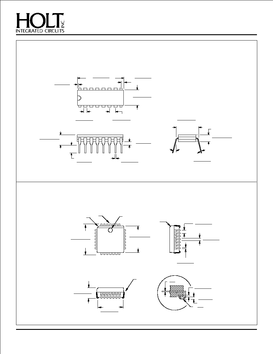
HI-318X PACKAGE DIMENSIONS
inches (millimeters)
Electrically isolated metal
heat sink on bottom of
package
(Connect to any ground or
power plane for optimum
thermal dissipation)

HI-318X PACKAGE DIMENSIONS
inches (millimeters)
HOLT INTEGRATED CIRCUITS
9
.0105 Ī .0015
(.2667 Ī .0381)
.295 Ī .004
(7.493 Ī .102)
0į to 8į
Detail A
Detail A
Bottom
View
Package Type: 16HWE
.090 Ī .010
(2.286 Ī .254)
.0025 Ī .0015
(.0635 Ī .0381)
.033 Ī .017
(.838 Ī .432)
.4065 Ī .0125
(10.325 Ī .318)
.405 Ī .008
(10.287 Ī .203)
.190 Ī .010
(4.826 Ī .254)
.050 Ī .010
(1.270 Ī .254)
.0165 Ī .0035
(.4191 Ī .0889)
Top View
.240 Ī .010
(6.096 Ī .254)
16-PIN PLASTIC SMALL OUTLINE (ESOIC) - WB
(Wide Body, Thermally Enhanced)
Package Type:
.125 MIN
(3.175 MIN
)
BASE
PLANE
SEATING
PLANE
.050 Ī .005
(1.270 Ī .127)
.295 Ī .010
(7.493 Ī .254)
PIN 1
.200 MAX
(5.080 MAX)
.018 Ī .002
(.457 Ī .051)
.100 BSC
(2.540 BSC)
.010 Ī .002
(.254 Ī .051)
.035 Ī .010
(.889 Ī .254)
.810 MAX
(20.574 MAX)
.300 Ī .010
(7.620 Ī .254)
16-PIN CERAMIC SIDE-BRAZED DIP
16C
Electrically isolated metal
heat sink on bottom of
package
(Connect to any ground or
power plane for optimum
thermal dissipation)
HI-318X PACKAGE DIMENSIONS
inches (millimeters)
HOLT INTEGRATED CIRCUITS
10
Package Type:
.045 x 45į
.453 Ī .003
(11.506 Ī .076)
SQ.
.490 Ī .005
(12.446 Ī .127)
SQ.
.045 x 45į
SEE DETAIL
A
.173 Ī .008
(4.394 Ī .203)
PIN NO. 1 IDENT
PIN NO. 1
.015 Ī .002
(.381 Ī .051)
DETAIL A
.020 MIN
(.508 MIN)
.025
.045
28-PIN PLASTIC PLCC
.410 Ī .020
(10.414 Ī .508)
.031 Ī .005
(.787 Ī .127)
.017 Ī .004
(.432 Ī .102)
.009
.011
.050 Ī .005
(1.27 Ī .127)
28J
R
Package Type:
.790 MAX.
(20.006 MAX.)
.200 MAX.
(5.080 MAX.)
.056 TYP.
(1.422 TYP.)
.100 Ī .010
(2.54 Ī .254)
.288 Ī .005
(7.315 Ī .125)
.050 MAX.
(1.27 MAX.)
.005 MIN.
(.127 MIN.)
.015 MIN.
(.381 MIN.)
0į to 15į
.010 Ī .002
(.254 Ī .051)
.180 MAX.
(4.572 MAX.)
.310 Ī .010
(7.874 Ī .254)
.125 MIN.
(3.175 MIN.)
.018 Ī .003
(.457 Ī .760)
16D
16-PIN CERDIP

Package Type:
.040 TYP.
(1.016) TYP.
.190 MAX.
(4.826) MAX.
.420 Ī .012
(10.668 Ī .305)
.588 Ī .008
(14.935 Ī .203)
.019 Ī .003
(.483 Ī .076)
.050 TYP.
(1.270) TYP.
.488 Ī .008
(12.395 Ī .203)
.450 Ī .008
(11.430 Ī .203)
.550 Ī .009
(13.970 Ī .229)
.520 Ī .012
(13.208 Ī .305)
31
32
1
2
.083 Ī .009
(2.108 Ī .229)
32-PIN J-LEAD CERQUAD
32U
HI-318X PACKAGE DIMENSIONS
inches (millimeters)
HOLT INTEGRATED CIRCUITS
11
Package Type:
.451 Ī .009
(11.455 Ī .229)
SQ.
.080 Ī .020
(2.032 Ī .508)
.040 x 45į 3PLS
(1.016 x 45į 3PLS)
.050 Ī .005
(1.270 Ī .127)
.025 Ī .003
(.635 Ī .076)
.050 BSC
(1.270 BSC)
.008R Ī .006
(.203R Ī .152)
.020 INDEX
(.508 INDEX)
PIN 1
28S
28-PIN CERAMIC LEADLESS CHIP CARRIER
PIN 1