 | –≠–ª–µ–∫—Ç—Ä–æ–Ω–Ω—ã–π –∫–æ–º–ø–æ–Ω–µ–Ω—Ç: HMC6352I | –°–∫–∞—á–∞—Ç—å:  PDF PDF  ZIP ZIP |
HMC6352
Advance Information
SENSOR PRODUCTS
DIGITAL COMPASS SOLUTION
Features
Fully Integrated Compass Module
2-Axis Magnetic Sensors with Electronics
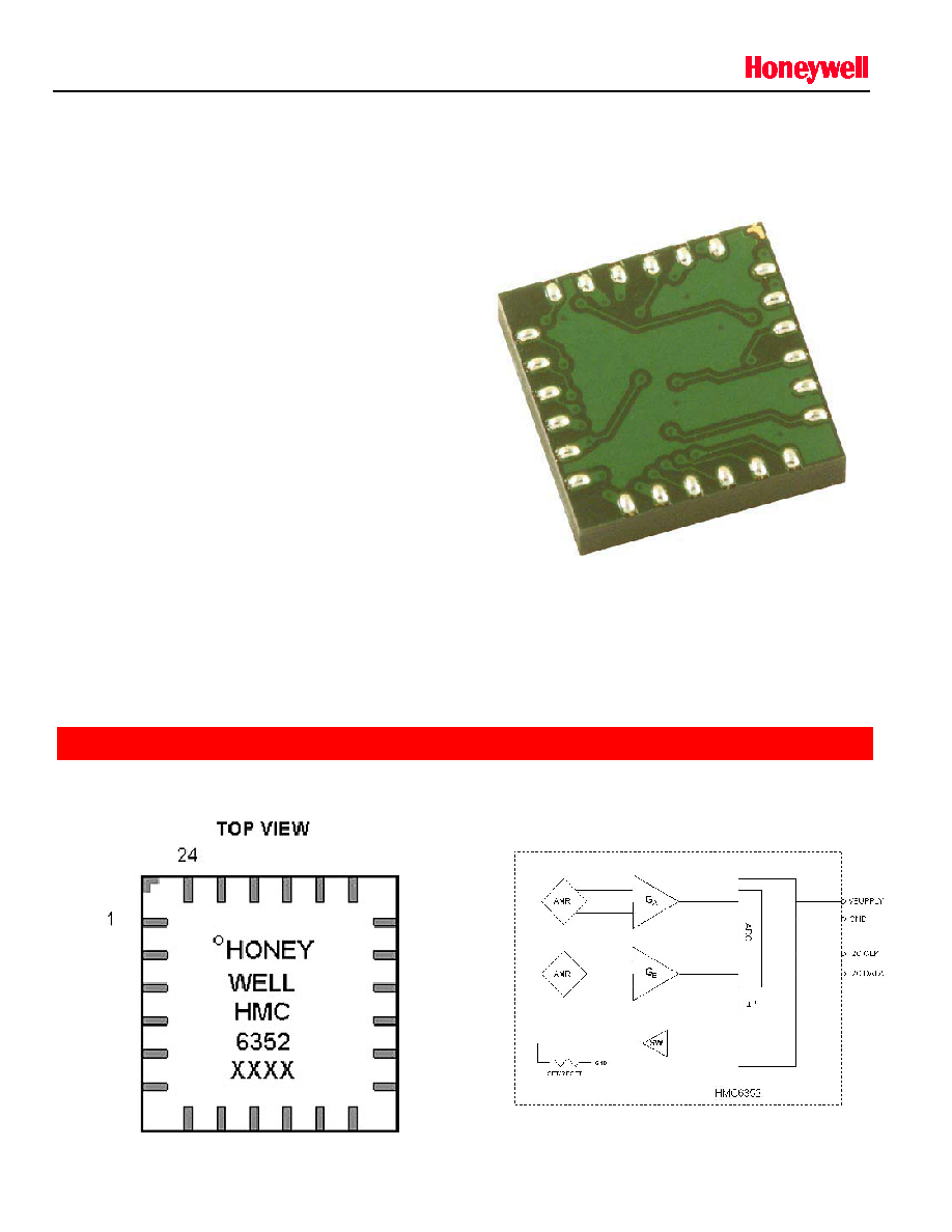
Miniature (6.5 by 6.5 by 1.4mm) 24-Pin LCC
Package
2.7 to 5.2 volt Supply Range
Accurate Compassing Capability
I
2
C Digital Interface
User Selectable Slave Address
Product Description
The Honeywell HMC6352 2-Axis Digital Integrated
Compass Solution combines a two-axis MR magnetic
field sensor design with the required analog and digital
support circuits for heading computation.
By combining the sensor elements and all the
processing electronics into a 6.5mm square LCC
package, designers will have the simplest solution to
integrate low cost and space efficient electronic
compasses for wireless phones, consumer electronics,
vehicle compassing, and antenna positioning.
BOTTOM VIEW
DIAGRAMS
PINOUT
BLOCK DIAGRAM
Solid State Electronics Center ∑ www.magneticsensors.com ∑ (800) 323-8295 ∑ Page 1
HMC6352
Advance Information
SENSOR PRODUCTS
HMC6352 SPECIFICATIONS
Characteristics
Conditions
(1)
Min
Typ
Max
Units
Supply Voltage
Vsupply to GND
2.7
3.0
5.2
Volts
Supply Current
Vsupply to GND
Steady State (Vsupply = 3.0V)
Steady State (Vsupply = 5.0V)
Dynamic Peaks
1
2
10
mA
mA
mA
Field Range
(2)
Total applied field
0.10
-
0.75
gauss
Heading Accuracy
HMC6352E
HMC6352
3
9
degRMS
Heading Resolution
0.3
deg
Heading
Repeatability
TBD
deg
Disturbing Field
Sensitivity starts to degrade.
Enable set/reset function to restore sensitivity.
20
gauss
Max. Exposed
Field
No permanent damage and set/reset function
restores performance.
10000
gauss
Operating
Temperature
Ambient
-20
70
∞C
Storage
Temperature
Ambient
-40
125
∞C
Output
Digital ≠ I
2
C Interface
Size
6.5 x 6.5 x 1.4
mm
Weight
TBD
grams
(1) Tested at 25∞C except stated otherwise.
(2) Field upper limit can be extended by using external resistors across CA1/CA2 and CB1/CB2.
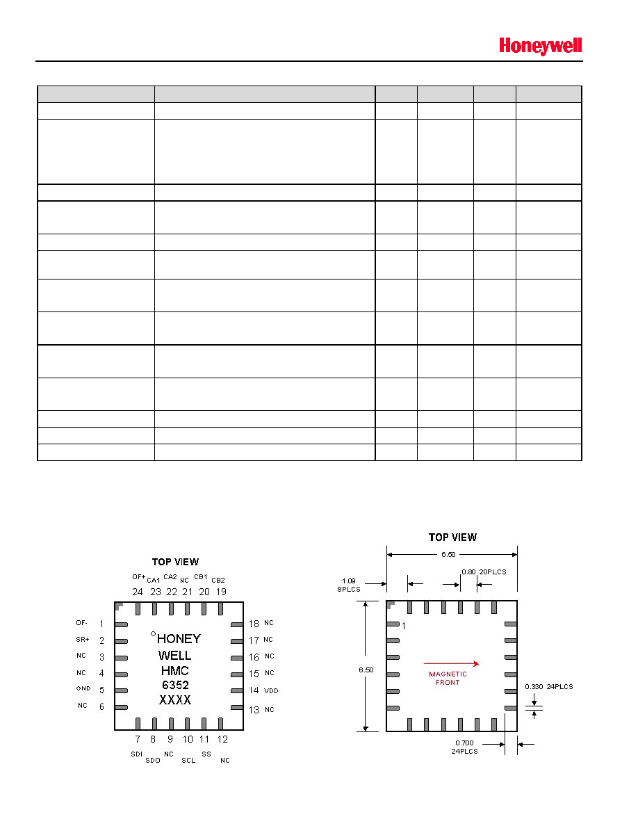
Pin Configuration/Package Dimensions
Solid State Electronics Center ∑ www.magneticsensors.com ∑ (800) 323-8295 ∑ Page 2

HMC6352
Advance Information
SENSOR PRODUCTS
Pin Descriptions
HMC6352
Pin
Name
Description
1
OF-
No User Connection (Offset Strap Negative)
2
SR+
No User Connection (Set/Reset Strap Positive)
3
NC
No User Connection
4
NC
No User Connection
5
GND
Supply/System Ground
6
NC
No User Connection
7
SDI
I2C Data Output (SPI Data In)
8
SDO
No User Connection (SPI Data Out)
9
PGM
No User Connection (Program Enable)
10
SCL
I2C Clock (SPI Clock)
11
SS
No User Connection (Slave Select)
12
NC
No User Connection
13
NC
No User Connection
14
VDD
Supply Voltage Positive Input (+2.7VDC to +5.0VDC)
15
NC
No User Connection
16
NC
No User Connection
17
NC
No User Connection
18
NC
No User Connection
19
CB2
Amplifier B Filter Capacitor Connection
20
CB1
Amplifier B Filter Capacitor Connection
21
NC
No User Connection
22
CA2
Amplifier A Filter Capacitor Connection
23
CA1
Amplifier A Filter Capacitor Connection
24
OF+
No User Connection (Offset Strap Positive)
Application Notes
The HMC6352 Integrated Compass Sensor circuit is composed of two magneto-resistive (MR) sensors with
orthogonal orientation for sensing the horizontal components of the earth's magnetic field (0 to 630 milli-gauss), plus
two amplifiers, a set/reset drive circuit, and a microprocessor ( P). Best accuracy is obtained in clean magnetic
environments (free air) and held level, or perpendicular to the gravitational direction. At worst case, each degree of tilt
from a level orientation could add two degrees of compass heading error. Magnetic errors can be introduced if
operated near strong magnetic sources such as microphone or speaker magnets, transformers in test equipment, and
CRT deflection yokes in video displays/monitors. These magnetic errors can typically be reduced or eliminated by
performing the calibration routine.
When locating the HMC6352 in dense printed circuit board designs, take precautions in location of this magnetic field
sensing device for soft-iron effects that bend the earth's magnetic field. These soft-iron effects are from ferrous
materials without residual magnetization and tend to be items like nickel-plating on SMT component contacts and
RFI/EMI shielding materials. The amount of stand-off of the HMC6352 from these soft-irons is heuristic and
dependant on the amount of material, material shape, and proximity.
A user calibration mode is available in the HMC6352 to diminish hard-iron effects of the end-user's (customer's)
location of the product. Hard-iron effects come from nearby ferrous materials with residual magnetism that buck or
boost the intensity of the earth's magnetic field, leading to heading errors. Such hard-iron effects come from vehicle
chassis, speaker magnets, and high current conductors or circuit traces.
I
2
C Communication Protocol
Solid State Electronics Center ∑ www.magneticsensors.com ∑ (800) 323-8295 ∑ Page 3
The HMC6352 communicates via a two-wire I
2
C bus system as a slave device. The HMC6352 uses a layered
protocol with the interface protocol defined by the I
2
C bus specification, and the lower command protocol defined by

HMC6352
Advance Information
SENSOR PRODUCTS
Honeywell. The data rate is the standard-mode 100kbps rate as defined in the I
2
C Bus Specification 2.1. The bus bit
format is an 8-bit Data/Address send and a 1-bit acknowledge bit. The format of the data bytes (payload) shall be
case sensitive ASCII characters or binary data to the HMC6352 slave, and binary data returned. Negative binary
values will be in two's complement form. The default (factory) HMC6352 slave address is 42(hex) for commands, or
43(hex) for response data bytes; and is a 7-bit address with the 0 bit (LSB) being the Read/Write selection.
The HMC6352 Serial Clock (SCL) and Serial Data (SDA) lines do not have internal pull-up resistors, and require
resistive pull-ups (Rp) between the master device and the HMC6352. Pull-up resistance values of about 10k ohms are
recommended with a nominal 3.0-volt supply voltage. Other values may be used as defined in the I
2
C Bus
Specification 2.1.
Command Protocol
The command protocol defines the content of the data (payload) bytes of I
2
C protocol sent by the master device (host
microprocessor), and the slave device (HMC6352).
After the master device sends the 7-bit slave address, the 1-bit Read/Write, and gets the 1-bit slave device
acknowledge bit returned; the next one to three sent data bytes are defined as the input command and argument
bytes. To conserve data traffic, all response data (Reads) will be context sensitive to the last command (Write) sent.
All commands shall have the address byte least significant bit cleared (factory default 42(hex)). These command then
follow with the ASCII command byte and command specific binary formatted argument bytes in the general form of:
(Command ASCII Byte) (Argument Binary MS Byte) (Argument Binary LS Byte)
The slave (HMC6352) shall provide the acknowledge bits between each data byte per the I
2
C protocol. Response
byte reads are done by sending the address byte (factory default 43(hex)) with the least significant bit set, and then
clocking back one or two response bytes, last command dependant. For example, an "A" command prompts the
HMC6352 to make a sensor measurement and to route all reads for a two byte compass heading or magnetometer
data response. Then all successive reads shall clock out two response bytes after sending the slave address byte.
Table 1 shows the HMC6352 command and response data flow.
Table 1 ≠ Interface Commands/Responses
Command
Byte
(ASCII)
Argument 1
Byte
(Binary)
Argument 2
Byte
(Binary)
Response 1
Byte
(Binary)
Response 2
Byte
(Binary)
Description
W
Address
Data
Write to EEPROM
R
Address
Data
Read from EEPROM
G
Address
Data
Write to RAM Register
g
Address
Data
Read from RAM Register
S
Enter Sleep Mode (Sleep)
W
Exit Sleep Mode (Wakeup)
O
Update Bridge Offsets (S/R Now)
C
Enter User Calibration Mode
E
Exit User Calibration Mode
L
Save Op Mode to EEPROM
A
MSB Data
LSB Data
Get Data. Calculate New Heading
Operational Modes
The HMC6352 has three operational modes plus the ability to enter/exit the non-operational (sleep) mode by
command. Sleep mode sends the internal microprocessor into clock shutdown to save power, and can be brought
back by the "W" command (wake). The "S" command returns the processor to sleep mode. The three operational
modes are defined by two bits in the internal HMC6352 operation mode register. If the master device sends the "L"
command, the current operational mode byte in the RAM register is loaded into the internal EEPROM register and
becomes the default operational mode on the next power-up. The operational mode selection byte RAM register
address is 74(hex).
Solid State Electronics Center ∑ www.magneticsensors.com ∑ (800) 323-8295 ∑ Page 4

HMC6352
Advance Information
SENSOR PRODUCTS
Standby Mode: (Operational Mode 0) This is the factory default mode. The HMC6352 waits for master device
commands or change in operational mode. Receiving an "A" command (get data) will make the HMC6352 perform a
measurement of sensors (magnetometers), compute the compensated magnetometer and heading data, and wait for
the next read or command. No new measurements are done until another "A" command is sent.
Query Mode: (Operational Mode 1) In this mode the internal processor waits for "A" commands (get data), makes the
measurements and computations, and waits for the next read command to output the data. After each read command,
the HMC6352 automatically performs another get data routine and updates the data registers. This mode is designed
to get data on demand without repeating "A" commands, and with the master device controlling the timing and data
throughput.
Continuous Mode: (Operational Mode 2) The HMC6352 performs continuous sensor measurements and data
computations at selectable rates of 1Hz, 5Hz, 10Hz, or 20Hz, and updates the output data bytes. Subsequent "A"
commands are un-necessary unless re-synchronization to the command is desired. Data reads automatically get the
most recent updates.
The continuous mode measurement rate is selected by two bits in the operational mode selection byte, along with the
mode selection and the periodic Set/Reset bit. The periodic Set/Reset function performs a re-alignment of the sensors
magnetic domains in case of sensor perming (magnetic upset event), operating temperature shifts, and normal
thermal agitation of the domains. Exposure of the HMC6352 to magnetic fields above 20 gauss (disturbing field
threshold) leads to possible measurement inaccuracy or "stuck" sensor readings until the set/reset function is
performed. With the periodic Set/Reset bit set, the set/reset function occurs every few minutes.
Operational Mode Byte Syntax
As described above, the HMC6352 operation mode, measurement rate, and periodic set/reset are selected and
stored both in a processor RAM register and in EEPROM. Upon power-up the EEPROM will transfer the saved
operational mode byte into register address 74(hex). The following is the byte format:
Bit 7 =0
Bits 6 and 5 (Continuous Mode Measurement Rate)
Bit 6
Bit 5
Description
0
0
1 Hz Measurement Rate
0
1
5 Hz Measurement Rate
1
0
10 Hz Measurement Rate
1
1
20 Hz Measurement Rate
Bit 4 (Periodic Set/Reset), 0 = Off, 1 = On
Bit 3 = 0
Bit 2 = 0
Bits 1 and 0 (Operational Mode Value)
Bit 1
Bit 0
Description
0
0
Standby Mode
0
1
Query Mode
1
0
Continuous Mode
1
1
Not Allowed
The total bit format for the Operational Mode Byte is shown below:
Bit 7 (MSB)
Bit 6
Bit 5
Bit 4
Bit 3
Bit 2
Bit 1
Bit 0 (LSB)
0
M. Rate_H
M. Rate_L
Per. S/R
0
0
Op Mode_H
Op Mode_L
Solid State Electronics Center ∑ www.magneticsensors.com ∑ (800) 323-8295 ∑ Page 5