
900240 Rev. B
3/01
HMR3000
Digital Compass Module
User's Guide
900240 Rev. B
3/01
page i
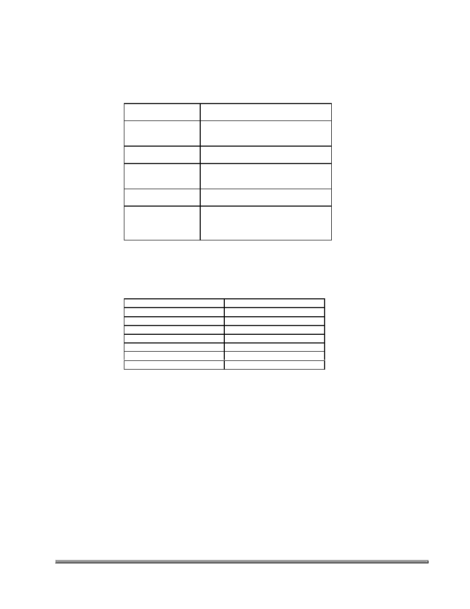
Packing List
Part Number
Items included
HMR3000-D00-232
HMR3000 RS 232 Circuit Card
Demo Software and
Users Manual CD-Rom
HMR3000-D00-485
HMR3000 RS 485 Circuit Card,
Users Manual CD Rom
HMR3000-D21-232
Housed Compass Module RS232
Demo Software Disk 1 and 2*
Users Manual CD Rom
HMR3000-D21-485
Housed Compass Module RS485
Users Manual CD Rom
HMR3000 Demo Kit
Housed Compass Module RS232
Demo Software Disk 1 and 2*
User's Manual CD Rom
Power supply and interface cable
*PC Demo Software Version 2.01 or higher
Parameter or Condition
Default Setting
Baud Rate
19200
Operation Mode
Run
Output Sentences
None
TC1 (filter 1 time constant)
4
Heading filter L value
0
Heading filter S value
0

900240 Rev. B
3/01
page ii
How to Set up HMR3000 Demo Unit
1) Connect the interface cable between the HMR3000 and COM port of a PC. Select the line voltage input
(110/220 V), turn the voltage selector to 9 V dc mark, and plug in the adapter to an electrical outlet.
2)
Install PC Demo Interface software on the PC by running Setup.exe from CD Rom. In Windows 95 or NT click
start, then Run and browse CD Rom to find Setup.exe. (Version 2.01 or higher)
3)
Double click on PC Demo Interface icon.
Select the correct COM port and 19200 baud rate (COM port is usually COM1).
Click the musical note button
Go to Serial Output tab and change the message rate on HPR sentence to 825.
Click on the display button
Note: You should have received PC Demo Interface Ver. 2.01 or higher. If you have an older version please update to
the latest version. Please call Honeywell customer services at 612-954-2888 if you need this newer version of software
Computer Requirements
Minimum:
PC 486/33MHz
Windows 3.1, Windows 95 or NT Operating System
VGA
2 Mb disk space (more for log file and captured data)
RS-232 serial port
Recommended:
P5/120MHz
Windows 3.1, Windows 95 or NT Operating System
SVGA 1024 x 768
Microsoft Excel (5.0 or greater) for capture and export of data (if desired)
Note: The Graphical output of the HMR3000 on PC Demo software may become sluggish if the PC has slow graphic
capability or if other applications are running in the background.

900240 Rev. B
3/01
page iii
Table of Contents
1.0
INTRODUCTION.............................................................................................1
2.0
GETTING TO KNOW HMR3000 PRODUCT....................................................1
2.1
I
DENTIFYING THE PRODUCT
............................................................................................1
2.2
S
ETTING UP
...................................................................................................................1
2.3
HMR3000 C
ONNECTION
D
IAGRAM
� C
OMPUTER
RS232
TO
HMR3000 ............................2
2.4
E
LECTRICAL
C
ONNECTIONS
...........................................................................................2
2.5
C
OMMUNICATION
-RS232 O
PTION
.................................................................................3
2.6
I
NSTALL
PC D
EMO
I
NTERFACE
.......................................................................................3
2.7
G
ETTING DATA OUT OF
HMR3000 ..................................................................................3
2.8
C
ONFIGURING
HMR3000 ...............................................................................................4
2.9
U
SING
PC D
EMO
I
NTERFACE
..........................................................................................4
2.10 C
OMMUNICATION
- RS485 O
PTION
................................................................................4
2.11 I
NSTALLATION
..............................................................................................................5
2.12 C
ALIBRATION
................................................................................................................5
3.0
OPERATION OF HMR3000 IN DETAIL ..........................................................6
3.1
GENERAL ...................................................................................................................6
3.2
HMR3000 ELECTRICAL BLOCK DIAGRAM..............................................................7
3.3
HMR3000 PROCESS CONTROL BLOCK DIAGRAM..................................................8
3.4
M
EASUREMENT
S
EQUENCE
............................................................................................8
3.5
I
NTERFACE
P
IN
D
ESCRIPTIONS
.......................................................................................8
3.6
C
OMMUNICATION
..........................................................................................................9
3.7
I
NPUT
...........................................................................................................................9
3.8
O
UTPUT
......................................................................................................................10
3.9
Q
UERY FOR
NMEA S
ENTENCES
...................................................................................10
3.10 F
ORMAT OF
NMEA S
ENTENCES
O
UTPUT
......................................................................10
3.11 C
HECKSUM
F
ILED
........................................................................................................13
3.12 W
ARNING AND
A
LARM
S
ETTINGS
.................................................................................13
4.0
CONFIGURATION PARAMETERS ...............................................................14
4.2
G
ENERAL
C
ONFIGURATION
P
ARAMETERS
.....................................................................15
4.3
M
EASUREMENT
P
ARAMETERS
......................................................................................16
4.4
S
ERIAL
I/O ..................................................................................................................19
5.0
DESCRIPTION OF HARDWARE INTERRUPT PINS.....................................21
6.0
ALGORITHM FOR THE NON-LINEAR HEADING FILTER..........................21
7.0
PHYSICAL DIMENSIONS............................................................................................................. 22

900240 Rev. B
3/01
page 1
1.0 INTRODUCTION
Thank you for purchasing Honeywell's HMR3000 Digital Compass Module. The HMR3000 uses Honeywell magnetic
sensors with proven MR technology and a two-axis tilt sensor to bring you the heading information. This electronically
gimbaled compass gives accurate heading even when the compass is tilted up to 40 degrees. The HMR3000 is reliable
and rugged since it does not contain any moving components and uses all surface mountable components. This low
power, small device is housed in a non-magnetic metallic enclosure that can be easily installed on any platform.
The HMR3000 is easy to use and extremely versatile. It allows the user to configure compass output to include any
combination of six NMEA standard messages and to change measurement parameters for the magnetometer to suit the
application. The sophisticated auto compass calibration routines will correct for the magnetic effects of the platform.
Wide dynamic range of the magnetometer (
�
1 G or 100
�
T) allows the HMR3000 to be useful in applications with large
local magnetic fields.
2.0 GETTING TO KNOW THE HMR3000 PRODUCT
2.1
Identifying the product
HMR3000 Compass module comes in three different options:
(1) Circuit board with RS 232 or RS485 electrical interface
(2) Housed Compass Module with RS232 or RS485 electrical interface
(3) Demonstration Kit (RS232 only)
The electrical interface of the compass module is clearly marked on the circuit board in option (1) and on the product
label in option (2). Option (3) only comes with RS232 electrical interface.
2.2
Setting up
Interface and power cables--Interface and power supply should be included in the Demonstration Kit (see Electrical
Connections in Section 2.4).
For other HMR3000 product options, a cable having a standard 9-pin D shell female connector should be wired
according to the pin-out defined below. Power should only be connected to either pin 9 or pin 8. It is sufficient to
connect the pins listed in Table 1 for most applications. However, pins 1, 4, 6 and 7 serve specific purposes in the
operation of HMR3000 and should be kept open (high logic state) in normal operation (see Table 2 for complete pin out
description). See Figure 1 for suggested cabling diagram for connection between HMR3000 and COM port of a
computer (IBM).
Name
In/Out
Pin
Description
TxD / A
Out
2
RS-232 transmit out / RS-485 transmit-receive signal
RxD / B
In
3
RS-232 receive in / RS-485 transmit-receive return
GND
In
5
Power and signal common
6-15V
In
9
Unregulated power input
5V
In
8
Regulated power input
Table 1. Pin assignment for typical operation of HMR3000 (See Table 2 for complete description)
Caution: Do NOT exceed +5.5V at regulated power input (pin 8). Higher voltages will damage components.