Transmissive Sensor
HOA1870
DESCRIPTION
FEATURES
Choice of phototransistor or photodarlington
output
∑
Accurate position sensing
∑
0.070 in.(1.78 mm) slot width
∑
18.0 in.(457 mm) min. 22 AWG UL 1007 wire
leads
∑
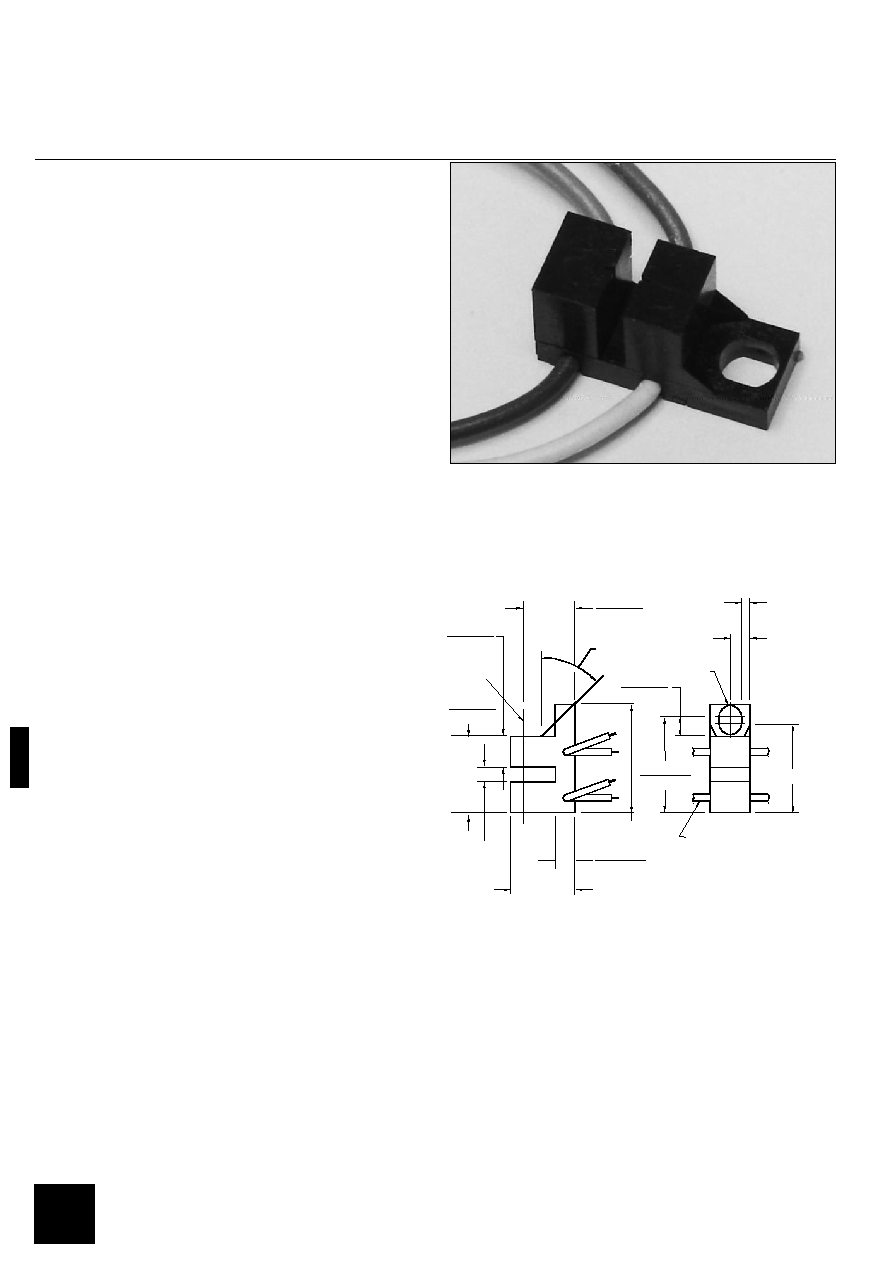
The HOA1870 series consists of an infrared emitting
diode facing an NPN silicon phototransistor
(HOA1870- 031) or photodarlington (HOA1870- 033)
encased in a black thermoplastic housing. Detector
switching takes place whenever an opaque object
passes through the slot between emitter and detector. A
minimum of 18.0 in.(457 mm) lead wires provides
alternate electrical connection when PC board mounting
is not possible. This device is ideal for use in
applications in which maximum position resolution is
desired. Both emitter and detector have a 0.006
in.(0.152 mm) x 0.040 in.(1.02 mm) vertical aperture.
The HOA1870 series employs plastic molded
components. For additional component information see
SEP8506, SDP8406 and SDP8106.
Housing material is polycarbonate. Housings are
soluble in chlorinated hydrocarbons and ketones.
Recommended cleaning agents are methanol and
isopropanol.
Wire color code and functions are:
Orange - IRED Anode
White - Detector Collector
Green - IRED Cathode
Blue - Detector Emitter
.052(1.32)
(2 PLCS)
.500(12.70
BLU
ORN
WHT
GRN
.125(3.17)
18" 26 AWG PVC MIN.
A = ORANGE
K = GREEN
E = BLUE
C = WHITE
.530(13.46)
.510(12.95)
.140(3.56)
.130(3.30)
.062(1.58)R
(2 PLCS)
.285(7.24)
.265(6.73)
.155(3.94)
.145(3.68)
.110(2.79)
.090(2.29)
.395(10.03)
.375(9.63)
.355(9.02)
.600(5.24)
.070(1.78)
45° (2 PLCS)
OPTICALC
L
DIM_043.ds4
INFRA--7.TIF
OUTLINE DIMENSIONS in inches (mm)
3 plc decimals
±0.010(0.25)
Tolerance
2 plc decimals
±0.020(0.51)
Honeywell reserves the right to make
changes in order to improve design and
supply the best products possible.
h
282

Transmissive Sensor
HOA1870
ELECTRICAL CHARACTERISTICS
UNITS
TEST CONDITIONS
MIN
PARAMETER
SYMBOL
TYP
MAX
IR EMITTER
DETECTOR
COUPLED CHARACTERISTICS
ABSOLUTE MAXIMUM RATINGS
(25°C Free-Air Temperature unless otherwise noted)
Operating Temperature Range
-40°C to 85°C
Storage Temperature Range
-40°C to 85°C
Soldering Temperature (5 sec)
240°C
IR EMITTER
Power Dissipation
100 mW [¿]
Reverse Voltage
3 V
Continuous Forward Current
50 mA
DETECTOR
TRANS.
DARLINGTON
Collector-Emitter Voltage
30 V
15 V
Emitter-Collector Voltage
5 V
5 V
Power Dissipation
100 mW [¿] 100 mW [¿]
Collector DC Current
30 mA
30 mA
SCHEMATIC
Honeywell reserves the right to make
changes in order to improve design and
supply the best products possible.
h
283

Transmissive Sensor
HOA1870
IRED Forward Bias Characteristics
gra_092.ds4
Forward voltage - V
F
o
r
w
a
r
d
c
u
r
r
e
n
t
-
m
A
0
10
20
30
40
50
60
70
80
90
100
0.8
1.0
1.2
1.4
1.6
1.8
2.0
Pulsed
condition
T
A
= 25 ∞C
T
A
= 80 ∞C
T
A
= -40 ∞C
Fig. 1
Non-Saturated Switching Time vs
Load Resistance
gra_096.ds4
Load resistance - Ohms
R
e
s
p
o
n
s
e
t
i
m
e
-
µ
s
1
10
100
1000
10
100
1000
10000
Phototransistor
Photodarlington
Fig. 2
Dark Current vs
Temperature
gra_301.cdr
Fig. 3
Collector Current vs
Ambient Temperature
gra_095.ds4
Free-air temperature - ∞C
N
o
r
m
a
l
i
z
e
d
c
o
l
l
e
c
t
o
r
c
u
r
r
e
n
t
0.0
0.6
1.2
-50
0.4
0.2
0.8
1.0
-25
0
25
50
100
75
Fig. 4
All Performance Curves Show Typical Values
Honeywell reserves the right to make
changes in order to improve design and
supply the best products possible.
h
284

Transmissive Sensor
HOA1870
Honeywell reserves the right to make
changes in order to improve design and
supply the best products possible.
h
285