
Transmissive Sensor
HOA1874
DESCRIPTION
FEATURES
Choice of phototransistor or photodarlington
output
∑
Three sensitivity ranges
∑
Choice of metal can package or plastic molded
components
∑
0.120 in.(3.05 mm) slot width
∑
The HOA1874 series consists of an infrared emitting
diode facing an NPN silicon phototransistor
(HOA1874- 001, - 002, - 011, - 012) or photodarlington
(HOA1874- 003, - 013) encased in a black thermoplastic
housing. Detector switching takes place whenever an
opaque object passes through the slot between emitter
and detector. The HOA1874- 001, - 002, and - 003 have
a 0.050 in.(1.27 mm) dia. detector aperture and employ
metal can packaged components, while the
HOA1874- 011,- 012, and - 013 have a 0.060 in.(1.52
mm) dia. detector aperture and contain plastic molded
components. For additional component information see
SE1450, SD1440, SD1410, SEP8506, SDP8406, and
SDP8106.
HOA1874-001, 002, 003 housing material is acetal
copolymer. HOA1874-011, 012, 013 housing material is
polyester. Housings are soluble in chlorinated
hydrocarbons and ketones. Recommended cleaning
agents are methanol and isopropanol.
DIM_046.cdr
INFRA-15.TIF
OUTLINE DIMENSIONS in inches (mm)
3 plc decimals
±0.010(0.25)
Tolerance
2 plc decimals
±0.020(0.51)
Honeywell reserves the right to make
changes in order to improve design and
supply the best products possible.
h
294

Transmissive Sensor
HOA1874
ELECTRICAL CHARACTERISTICS
UNITS
TEST CONDITIONS
MIN
PARAMETER
SYMBOL
TYP
MAX
IR EMITTER
DETECTOR
COUPLED CHARACTERISTICS
ABSOLUTE MAXIMUM RATINGS
(25°C Free-Air Temperature unless otherwise noted)
ABSOLUTE MAXIMUM RATINGS (continued)
Operating Temperature Range
HOA1874-001, -002, -003
-55°C to 100°C
HOA1874-011, -012, -013
-40°C to 85°C
Storage Temperature Range
HOA1874-001, -002, -003
-55°C to 125°C
HOA1874-011, -012, -013
-40°C to 85°C
Soldering Temperature
HOA1874-001, -002, -003
260°C (10 sec)
HOA1874-011, -012, -013
240°C (5 sec)
IR EMITTER
Power Dissipation:
HOA1874-001, -002, -003
75 mW
HOA1874-011, -012, -013
100 mW
Reverse Voltage
3 V
Continuous Forward Current
50 mA
DETECTOR
TRANS.
DARLINGTON
Collector-Emitter Voltage
30 V
15 V
Emitter-Collector Voltage
5 V
5 V
Power Dissipation:
HOA1874-001, -002, -003
75 mW [¿]
75 mW [¿]
HOA1874-011, -012, -013
100 mW [¡] 100 mW [¡]
Collector DC Current
30 mA
30 mA
Notes
1. Derate linearly at 0.71 mW/°C above 25°C.
2. Derate linearly at 0.78 mW/°C above 25°C.
Honeywell reserves the right to make
changes in order to improve design and
supply the best products possible.
h
295
Transmissive Sensor
HOA1874
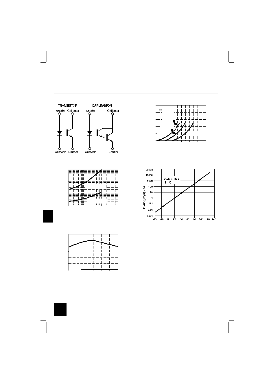
SCHEMATIC
sch_027.cdr
IRED Forward Bias Characteristics
gra_092.ds4
Forward voltage - V
F
o
r
w
a
r
d
c
u
r
r
e
n
t
-
m
A
0
10
20
30
40
50
60
70
80
90
100
0.8
1.0
1.2
1.4
1.6
1.8
2.0
Pulsed
condition
T
A
= 25 ∞C
T
A
= 80 ∞C
T
A
= -40 ∞C
Fig. 1
Non-Saturated Switching Time vs
Load Resistance
gra_096.ds4
Load resistance - Ohms
R
e
s
p
o
n
s
e
t
i
m
e
-
µ
s
1
10
100
1000
10
100
1000
10000
Phototransistor
Photodarlington
Fig. 2
Dark Current vs
Temperature
gra_303.cdr
Fig. 3
Collector Current vs
Ambient Temperature
gra_095.ds4
Free-air temperature - ∞C
N
o
r
m
a
l
i
z
e
d
c
o
l
l
e
c
t
o
r
c
u
r
r
e
n
t
0.0
0.6
1.2
-50
0.4
0.2
0.8
1.0
-25
0
25
50
100
75
Fig. 4
All Performance Curves Show Typical Values
Honeywell reserves the right to make
changes in order to improve design and
supply the best products possible.
h
296

Transmissive Sensor
HOA1874
Honeywell reserves the right to make
changes in order to improve design and
supply the best products possible.
h
297