
Transmissive Sensor
HOA1883
DESCRIPTION
FEATURES
Choice of phototransistor or photodarlington
output
∑
Wide lead spacing
∑
0.060 in.(1.52 mm)dia. detector aperture
∑
0.140 in.(3.56 mm) slot width
∑
The HOA1883 series consists of an infrared emitting
diode facing an NPN silicon phototransistor
(HOA1883- 011, - 012) or photodarlington
(HOA1883- 013) encased in a black thermoplastic
housing. Detector switching takes place whenever an
opaque object passes through the slot between emitter
and detector. The HOA1883 series employs plastic
molded components. For additional component
information see SEP8506, SDP8406, and SDP8106.
Housing material is polycarbonate. Housings are
soluble in chlorinated hydrocarbons and ketones.
Recommended cleaning agents are methanol and
isopropanol.
A
K
E
C
.020(0.51) SQ.
.250(6.36)
.125(3.18)
.100(2.54)
.050(1.27)
.340(8.64)
.490(12.45)
.140(3.56)
.175(4.44)
.300(7.62)
.100(2.54)
.325(8.25)
.250(6.35)
~ ~
~
~
C
L
MIN.
S
+
+
E
OPTICAL
DIM_068.ds4
INFRA-41.TIF
OUTLINE DIMENSIONS in inches (mm)
3 plc decimals
±0.010(0.25)
Tolerance
2 plc decimals
±0.020(0.51)
Honeywell reserves the right to make
changes in order to improve design and
supply the best products possible.
h
322
Transmissive Sensor
HOA1883
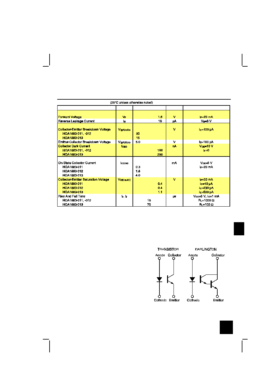
ELECTRICAL CHARACTERISTICS
UNITS
TEST CONDITIONS
MIN
PARAMETER
SYMBOL
TYP
MAX
IR EMITTER
DETECTOR
COUPLED CHARACTERISTICS
ABSOLUTE MAXIMUM RATINGS
(25°C Free-Air Temperature unless otherwise noted)
Operating Temperature Range
-40°C to 85°C
Storage Temperature Range
-40°C to 85°C
Soldering Temperature (5 sec)
240°C
IR EMITTER
Power Dissipation
100 mW [¿]
Reverse Voltage
3 V
Continuous Forward Current
50 mA
DETECTOR
TRANS.
DARLINGTON
Collector-Emitter Voltage
30 V
15 V
Emitter-Collector Voltage
5 V
5 V
Power Dissipation
100 mW [¿] 100 mW [¿]
Notes
1. Derate linearly at 0.78 mW/°C above 25°C.
SCHEMATIC
Honeywell reserves the right to make
changes in order to improve design and
supply the best products possible.
h
323
Transmissive Sensor
HOA1883
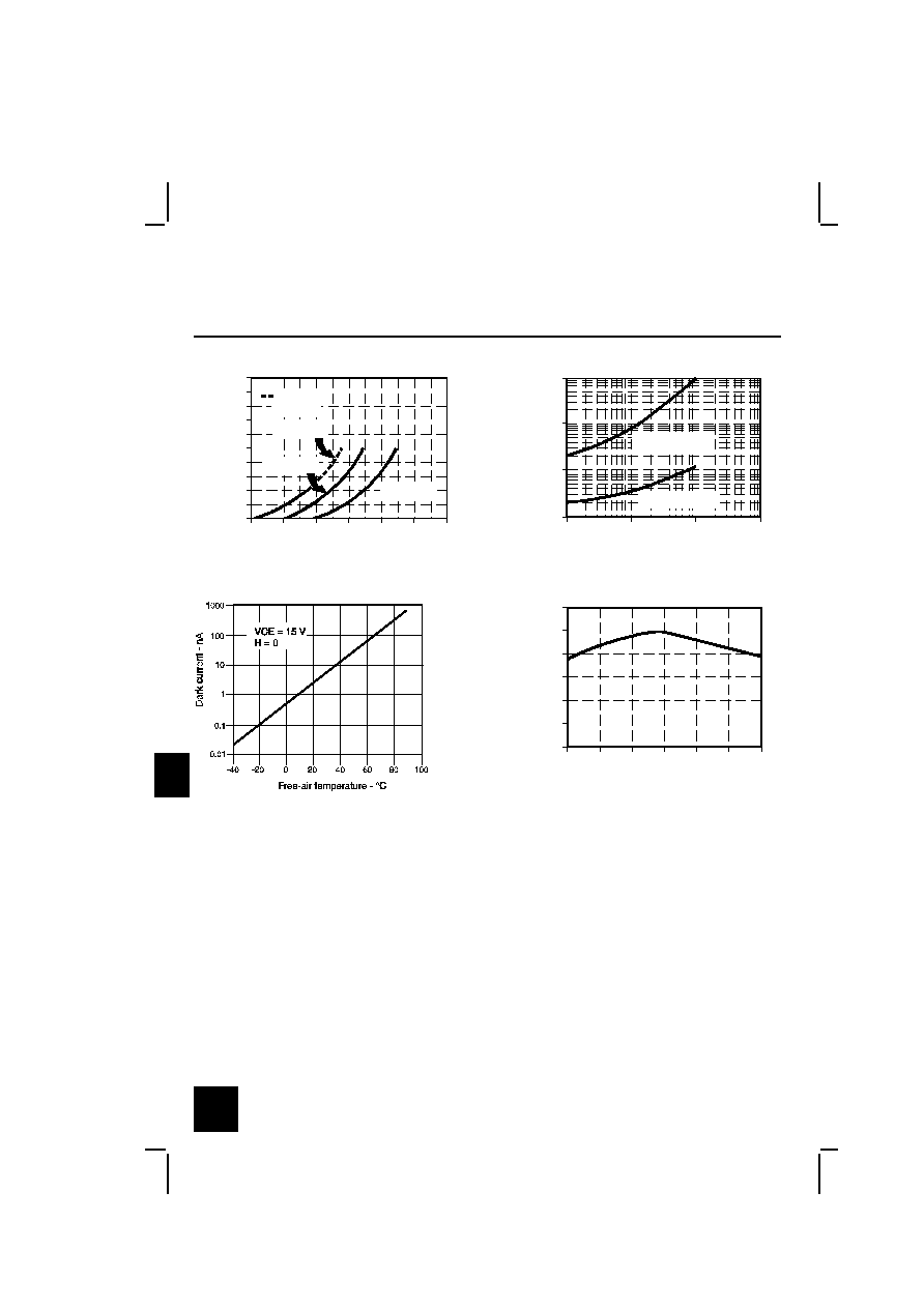
IRED Forward Bias Characteristics
gra_092.ds4
Forward voltage - V
F
o
r
w
a
r
d
c
u
r
r
e
n
t
-
m
A
0
10
20
30
40
50
60
70
80
90
100
0.8
1.0
1.2
1.4
1.6
1.8
2.0
Pulsed
condition
T
A
= 25 ∞C
T
A
= 80 ∞C
T
A
= -40 ∞C
Fig. 1
Non-Saturated Switching Time vs
Load Resistance
gra_096.ds4
Load resistance - Ohms
R
e
s
p
o
n
s
e
t
i
m
e
-
µ
s
1
10
100
1000
10
100
1000
10000
Phototransistor
Photodarlington
Fig. 2
Dark Current vs
Temperature
gra_301.cdr
Fig. 3
Collector Current vs
Ambient Temperature
gra_095.ds4
Free-air temperature - ∞C
N
o
r
m
a
l
i
z
e
d
c
o
l
l
e
c
t
o
r
c
u
r
r
e
n
t
0.0
0.6
1.2
-50
0.4
0.2
0.8
1.0
-25
0
25
50
100
75
Fig. 4
All Performance Curves Show Typical Values
Honeywell reserves the right to make
changes in order to improve design and
supply the best products possible.
h
324

Transmissive Sensor
HOA1883
Honeywell reserves the right to make
changes in order to improve design and
supply the best products possible.
h
325