 | –≠–ª–µ–∫—Ç—Ä–æ–Ω–Ω—ã–π –∫–æ–º–ø–æ–Ω–µ–Ω—Ç: GL6851 | –°–∫–∞—á–∞—Ç—å:  PDF PDF  ZIP ZIP |
GL6851
1
GL6851
TWO TONE RINGER
Description
The GL6851 tone ringer is a monolithic device,
which incorporates two oscillators, an output
amplifier and a power supply control circuit. The
oscillator frequencies can be adjusted over a wide
range by selection of external components. One
oscillator, normally operated at a low frequency,
causes the second oscillator to alternate between
its nominal frequency, and a related higher
frequency. The resulting output is a distinct
warbling tone. The output amplifier will drive
either a transformer coupled loudspeaker or a
piezo-ceramic transducer. The device can be
powered from a telephone line or a fixed d.c.
supply. The GL6851 has provision for
adjustment of the supply initiation current.
Pin Configuration
Features
∑ Low current consumption.
∑ Designed for telephone bell replacement.
∑ Small size MINIDIP package.
∑ Adjustable 2- frequency tone.
∑ Built-in hysteresis prevents false triggering and rotary dial CHIRPS.
∑ Alarms or other alerting devices.
∑ Adjustable for reduced supply initiation current
∑ Include ESD protection.
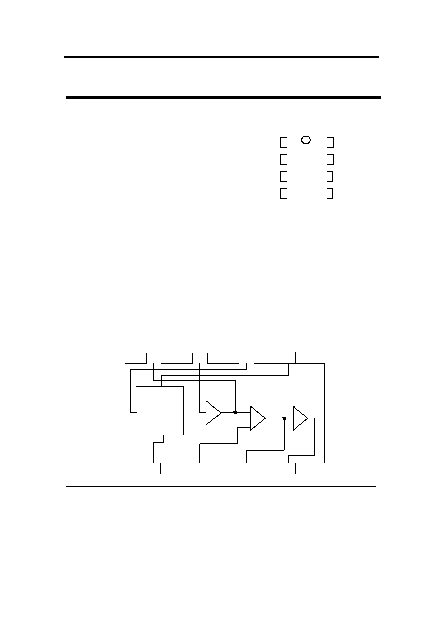
Block Diagram
1
2
3
4
5
6
7
8
GL6851
VCC
RSL
LOWOSC_1
LOWOSC_2
OUTPUT
HIGHOSC_2
HIGHOSC_1
GND
5
6
7
8
4
3
2
1
POWER SUPPLY
CONTROL CIRCUIT
(WITH HYSTERESIS)
LOW FREQUENCY
OSCILLATOR
HIGH FREQUENCY
OSCILLATOR
OUTPUT
AMPLIFIER

GL6851
2
Absolute Maximum Ratings (Ta = 25° …
)
CHARACTERISTICS
SYMBOL
VALUE
UNIT
Supply Voltage
Power Dissipation
Operating Temperature
Storage Temperature
V
CC
Po
Topr
Tstg
30
400
-25 to 65
-65 to 150
V
mW
° …
° …
Electrical Characteristics (Ta = 25° …
)
CHARACTERISTICS
SYMBOL
TEST CONDITION
MIN
TYP
MAX UNIT
Operating Supply Voltage
V
CC
-
-
29.0
V
Initiation Supply Voltage
1
V
SI
17
19
21
V
Initiation Supply Current
1
I
SI
0.9
2.0
3.7
mA
Sustaining Voltage
2
V
SUS
9.7
11.0
12.0
V
Sustaining Current
2
I
SUS
0.4
1.0
2.0
mA
Output Voltage High
V
OH
V
CC
=21V, I
8
=-10mA
Pin6=6V,Pin7=GND
17
19
21
V
Output Voltage Low
V
OL
V
CC
=21V, I
8
= 10mA
Pin6=GND,Pin7=6V
-
-
2
V
High Frequency 1
High Frequency 2
Low Frequency
f
H1
f
H2
f
L
R3=191K,C3=6800pF
R3=191K,C3=6800pF
R2=165K,C2=0.47µF
461
576
9.0
512
640
10
563
704
11.0
Hz
Hz
Hz
* NOTE
1. Initial supply voltage (V
SI
) is the supply voltage required to start the tone ringer oscillation.
2. Sustaining voltage (V
SUS
) in the supply voltage required to maintain oscillation.

GL6851
3
PIN DESCRIPTION
PIN NUMBER
PIN FUNCTION
DESCRIPTION
PIN 1
VCC
Operating supply D.C. voltage rectified
from ringing signal.
PIN2
RSL
Initiation current programming Pin.
(Must be connected)
PIN3
LOWOSC_1
PIN 4
LOWOSC_2
Low Frequency Time Constant Adjustment pins
f
L
is controlled externally by R
2
and C
2
f
L
= 1/1.289R
2
C
2
PIN 5
GND
Ground
PIN 6
HIGHOSC_1
PIN 7
HIGHOSC_2
High Frequency Time Constant Adjustment Pins
f
H1
and f
H2
are controlled externally by R
3
and C
3
.
f
H1
=1/1.504R
3
C
3
, f
H2
= 1/1.203R
3
C
3
PIN 8
OUTPUT
Tone output
APPLICATON CIRCUIT
7K - 13K
1300 : 8 ohm
TIP
C1 R1
RING
C4
D1
R2
C2
C5
R3
C3
15K
10K
VOLUME
C1 = 0.9uF
C2 = 0.47uF
C3 = 6.8nF
C4 = 22µf / 35V
C5 = 0.22 uF
D1 = 29 V
R1 = 560 ohm
R2 = 165 kohm
R3 = 191 kohm
1
2
3
4
5
6
7
8
GL 6851
RSL