 | –≠–ª–µ–∫—Ç—Ä–æ–Ω–Ω—ã–π –∫–æ–º–ø–æ–Ω–µ–Ω—Ç: HY6330 | –°–∫–∞—á–∞—Ç—å:  PDF PDF  ZIP ZIP |

32 ∑ 400 Hot Springs Road, Carson City NV 89706 ∑ (775) 883-0820 ∑ Fax (775) 883-0827 ∑ www.hytek.com
HY6330
Laser Diode Driver
Description:
The HY6330 Laser Diode Driver
is a program-
mable voltage controlled constant current transcon-
ductance amplifier with optical feedback.
The HY6330 is used in applications that require a
stable, selectable current source to drive a laser diode.
The current is selectable from zero to over 170mA. Con-
stant optical output power can be maintained using feed-
back from a back facet photodetector. Optical output
can also be monitored using the voltage proportional out-
put provided. The HY6330 comes in 10-pin thruhole or
surface mount packages.
The HY6330 is designed for applications requiring
constant current drive for the operation of laser diodes
such as pump sources for EDFA's telecom lasers, and
diode pumped semiconductors.
Features:
F
F
F
F
F
Adjustable current to 170mA @ 5Volts
F
F
F
F
F
Enable/disable pin
F
F
F
F
F
For common cathode or isolated laser diode
current drive
F
Very small size
F
Thru-hole or surface-mount package option
Switchable Constant Current Laser Diode Driver
FIGURE 1
TEC Controllers
Laser Diode Drivers
Micro-heaters
FIGURE 2
400 Hot Springs Road, Carson City NV 89706 ∑ (775) 883-0820 ∑ Fax (775) 883-0827 ∑ www.hytek.com ∑ 33
HY6330
Laser Diode Driver
Signal Descriptions
V
CC
Input power supply, +5 Volts typical
EN
The Enable pin is used to enable/disable the output. When the Enable pin is connected to ground, the
output is disabled. When this pin is connected to V
CC
or left open, the laser current is enabled, allowing
current to flow through the laser diode.
CC
The current is set by the voltage at the current control input. The voltage, on the current control input,
programs the laser diode drive current, I
OUT
. When the input is at GND the modulation current is zero.
Maximum laser current occurs when this voltage is V
CC
.
GND
Ground return for V
CC
(input power supply).
FB
This high impedance input is used with a photodetector to control Output Current.
FEN
At V
CC
this input disables Feedback on Pin 3, which allows diode current to be set by Pin 6.
I
OUT
This Output provides drive current to the laser diode; (anode/positive; connect cathode to ground). Maxi-
mum drive current is dependent upon laser diode impedance and power supply input voltage.
V
OPT
The optical monitor voltage is proportional to the optical output power of the laser diode as sensed by a
backfacet photodetector over the range of 1
µ
A to 1mA.
Input Specifications
Power Supply Input (V
CC
): Pins 1, 10
+5 to +8V @250mA max.
Drive Enable (EN): Pin 9
GND (off, disable), V
CC
or open
(on, enable)
Current Control (CC): Pin 6
0 to 200mA for input voltage 0 to V
CC
Ground (GND): Pins 5, 7
Power supply ground
Feedback-Optical (FB): Pin 3
0 <FB <V
CC
Feedback-Enable (FEN): Pin 8
V
CC
(disable), GND or open (enable)
Output Specifications
Laser Diode Current Drive (I
OUT
): Pin 2
0 to 170mA @ 5V, 0 to 250mA @ 8V
Optical Output Monitor (V
OPT
): Pin 4
Range 0≠4V
Environmental Conditions
Operating Temperature
≠20∞C to 100∞C (case)
Storage Temperature
≠65∞C to 150∞C (case)
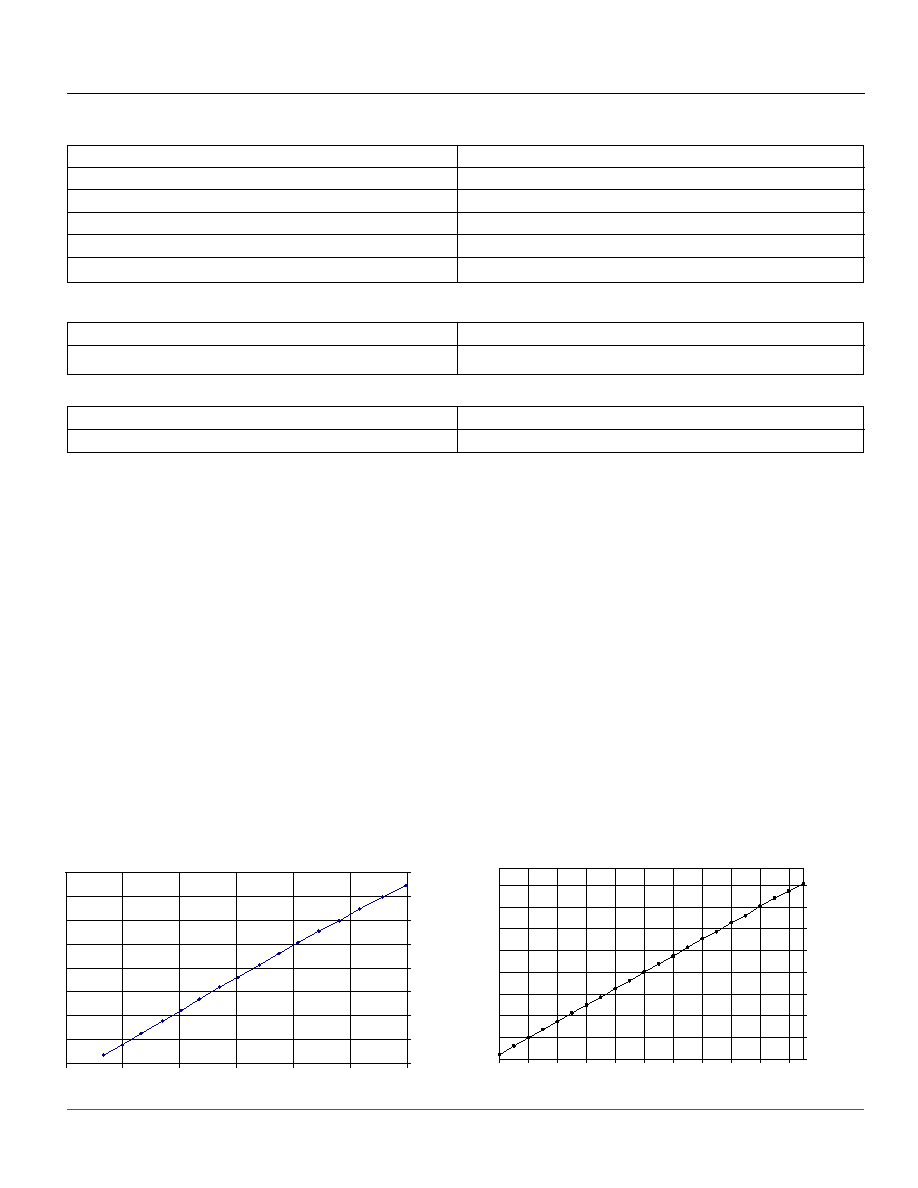
INPUT VOLTAGE VS OUTPUT CURRENT
Vcc = 5 VDC
0
0.02
0.04
0.06
0.08
0.1
0.12
0.14
0.16
2
2.5
3
3.5
4
4.5
5
INPUT VOLTAGE PIN 6
OUTPUT CURRENT (AMPS)
INPUT VOLTAGE VS OUTPUT CURRENT
Vcc= 7 VDC
0.000
0.025
0.050
0.075
0.100
0.125
0.150
0.175
0.200
3.5
3.8
4.1
4.5
4.9
5.2
5.5
5.9
6.2
6.6
6.9
INPUT VOLTAGE PIN 6
LOAD CURRENT (AMPS)

34 ∑ 400 Hot Springs Road, Carson City NV 89706 ∑ (775) 883-0820 ∑ Fax (775) 883-0827 ∑ www.hytek.com
HY6330
Laser Diode Driver
Automatic Power Control (APC)
The HY6330 can be used in Constant Current Mode or in Constant Power Mode. In Constant Current Mode, a program-
ming voltage applied at pin 6, the Current Control input, sets a constant current output level to the laser diode which
does not vary with changes in load (with constant Vcc supply voltage). In Constant Power Mode, the feedback current
from a laser's backfacet photodetector (normally reverse biased as shown below) is used to adjust HY6330 output cur-
rent to help oppose reduction in laser diode light output caused by aging.
Feedback is enabled by tying pin 8, feedback enable (FEN), to ground or leaving open. A voltage proportional to the
magnitude of feedback current can be monitored at pin 4, optical feedback output (Vopt). This voltage will provide a
relative measure of the laser's optical output.
Feedback from the laser's reverse biased backfacet photodetector is directly connected into pin 3, Optical Feedback In-
put (FB). There is an internal 20k ohm input impedance from this point to ground. As current feedback can vary widely
among different models of laser diodes, from micro to milliamps, the voltage presented at pin 3 usually must be ad-
justed with a parallel external resistor to ground.
Increasing the voltage at pin 3 will decrease the current drive to the laser diode. So, as the laser ages and light output
falls, feedback current and the voltage at pin 3 will also fall thereby increasing current drive to the laser diode to main-
tain a more constant light output. Feedback voltage will generally range between 0 and 1.5V.
As feedback will limit the maximum current output available to the laser diode, it should be adjusted down so that there
is only sufficient range to counteract laser aging effects. To accomplish this follow this procedure:
- Connect the HY6330 as depicted in Figure 1 except do not connect pin 3, optical feedback.
- Increase Current Control Input (CC), pin 6, from 0 volts until desired light output from the laser diode is achieved.
- Connect optical feedback from the reverse biased back facet photodetector of the laser to pin 3 Feedback (FB) input.
- Using 10k
potentiometer from Pin 3 to ground (Figure 1) attenuate the feedback voltage at Pin 3 until laser diode
light output is reduced by the amount predicted by the laser manufacturer over its expected life. e.g. if expected aging
light reduction is given as 15%, reduce feedback voltage until laser diode light output is reduced by 15% to 20%.
- Increase Current Control Input (CC), pin 6, until desired light output is restored.
The reduced feedback from the laser diode's backfacet photodetector as the laser ages will cause the HY6330 to in-
crease current drive to counteract this effect. To maintain light output precisely, some gain must be added to the opti-
cal feedback. The required gain, positive or negative, is highly dependent on the particular laser diode in use.