
400 Hot Springs Road, Carson City NV 89706 ∑ (775) 883-0820 ∑ Fax (775) 883-0827 ∑ www.hytek.com ∑ 33
HY-7110
Micro-heater
TEC
Controllers
Laser
D
iode
Drivers
Micro-heaters
Miniature Proportionally
Controlled Heater
Description:
The HY7110 is a miniature proportionally controlled heater
whose temperature can be programmed with a single exter-
nal resistor. This device is ideally suited for regulating the
temperature of sensitive electronic components such as mi-
crowave filters, optical waveguides, multiplexers and crystal
oscillators. The HY7110 in a ceramic package can supply
up to 28 Watts of power from an unregulated 28 Volt supply.
Operating characteristics:
Characteristic
Symbol
Min
Max
Unit
Supply Voltage
V
DD
+8
+35
Vdc
(Pin 1 to Pin 2)
Steady State Supply
I
S
0.015
1.0
Adc
Current @ V
DD
= +35 Vdc
Temperature variation over
T
V
2
įC
operating voltage
Temperature variation
T
L
10
įC
with load
Control Temperature Range
T
C
50
100
įC
Control Resistor Value
R
C
0
35K
Pin 3 to Pin 4 (See Figure 1)
Maximum Control
T
MAX
110
įC
Temperature when Rc = 0
Turn on power at start-up
P
D
25
28
Watts
@V
DD
= +28 Volts
Maximum ratings:
Rating
Symbol
Value
Unit
Supply Voltage
V
DD
35
Vdc
Reverse Voltage
V
R
≠50
Vdc
Power Dissipation
P
D
35
Watts
Operating Temperature (Case)
T
MAX/MIN
100/≠20
įC
Storage Temperature Range
≠65 to +150
įC
OUTLINE DIMENSIONS
BERYLLIA BASE
TWO TIMES ACTUAL SIZE
0.018" diameter
Cu with Au flash
Features:
Beryllia base for good thermal conduction
Regulation temperature from 40įC to 100įC
Electrically isolated from the case
Epoxy sealed
Hermetically sealed and military screened
units available
34 ∑ 400 Hot Springs Road, Carson City NV 89706 ∑ (775) 883-0820 ∑ Fax (775) 883-0827 ∑ www.hytek.com
HY-7110
Micro-Heater
NOTES:
1. Optimum heat transfer between the HY7110 and the device being heated occurs when a thermal compound, such as
Dow Corning 340, is applied to the mounting surface of the heater.
2. Operation is possible from 100 įC to 120įC, however electrical performance is not guaranteed.
3. Special environmental and electrical screening is available on request.
4. Special custom engineered micro-heater available on request.
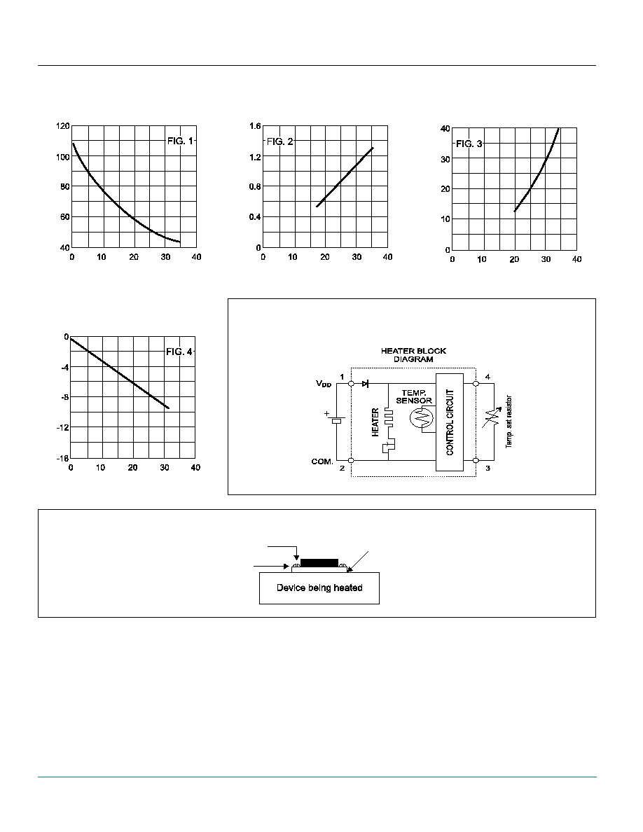
HEATER BLOCK
DIAGRAM
TYPICAL
BASE TEMPERATURE
VS
CONTROL RESISTOR
BASE TEMPERA
TURE įC
MAX START-UP CURRENT
VS
SUPPLY VOLTAGE
SUPPL
Y CURRENT (AMPS)
MAX THERMAL POWER
AVAILABLE
VS
SUPPLY VOLTAGE
OUTPUT POWER (W
A
TTS)
TYPICAL BASE TEMPERATURE
LOSS WITH
POWER DISSIPATION
TEMPERA
TURE CHANGE įC
MOUNTING THE HY7110 HEATER
Thermal compound
between surfaces
Do not overtighten the mounting screws.
This may result in breaking the ceramic substrate.
#2-56 mounting
screws
Electrical pin
not shown
for clarity
CONTROL RESISTOR R
C
IN K
SUPPLY VOLTAGE (VOLTS D.C.)
SUPPLY VOLTAGE (VOLTS D.C.)
POWER OUTPUT (WATTS)
FROM HY7110