Dec-08-2003
1
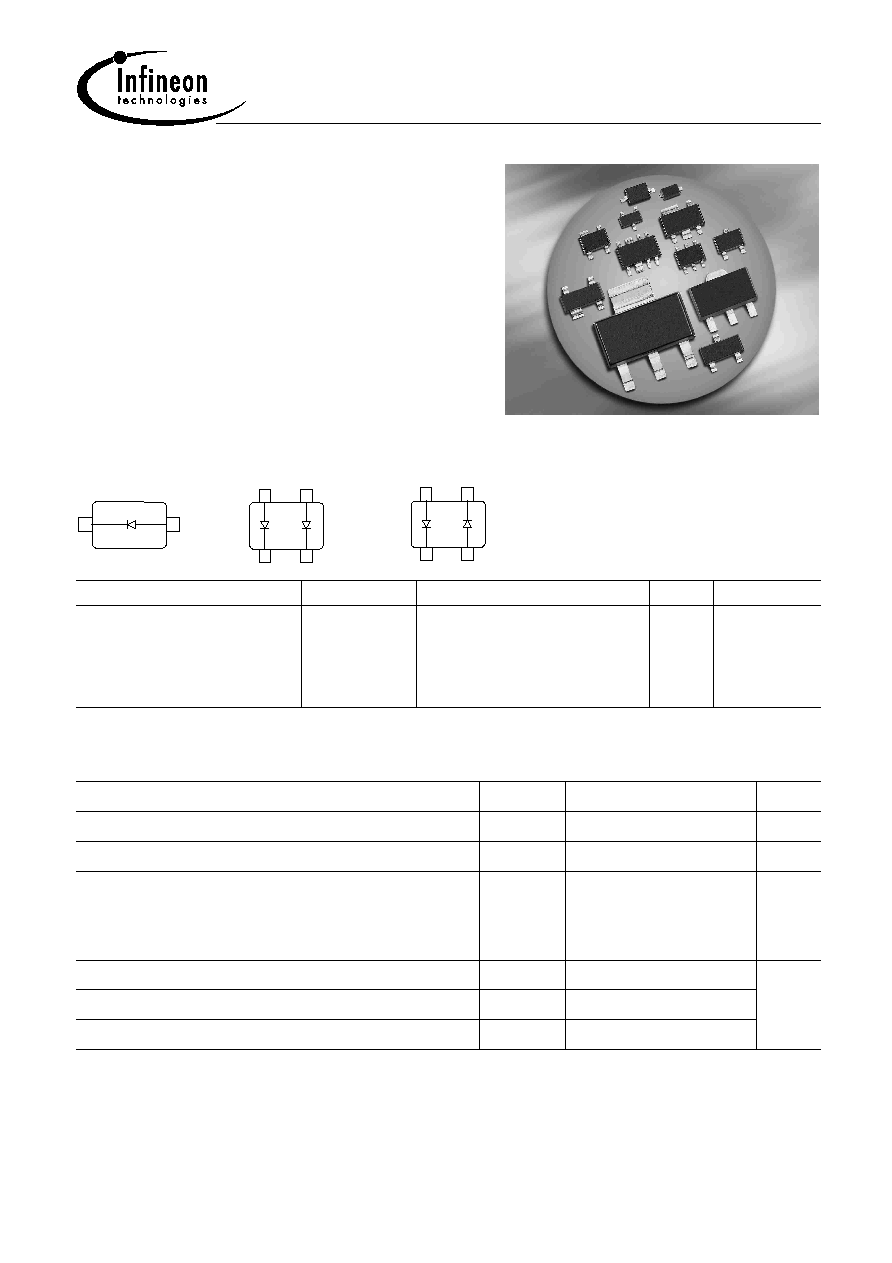
BAR88...
Silicon PIN Diode
∑
Optimized for low current antenna switches
in hand held applications
∑
Very low forward resistance
(typ. 1.5
@ I
F
= 1 mA)
∑
Low capacitance at zero volt reverse bias
at frequencies above 1 GHz (typ. 0.28 pF)
∑
Very low signal distortion
BAR88-02L
BAR88-02V
BAR88-07L4
BAR88-099L4
1
2
1
D 2
2
3
4
D 1
1
D 2
2
3
4
D 1
Type
Package
Configuration
L
S
(nH)
Marking
BAR88-02L
BAR88-02V
BAR88-07L4*
BAR88-099L4*
TSLP-2-1
SC79
TSLP-4-4
TSLP-4-4
single, leadless
single
parallel pair, leadless
anti-parallel pair, leadless
0.4
0.6
0.4
0.4
UU
U
UT
US
* Preliminary Data
Maximum Ratings at T
A
= 25∞C, unless otherwise specified
Parameter
Symbol
Value
Unit
Diode reverse voltage
V
R
80
V
Forward current
I
F
100
mA
Total power dissipation
BAR88-02L, -07L4, -099L4 T
s
133∞C
BAR88-02V, T
s
123∞C
P
tot
250
250
mW
Junction temperature
T
j
150
∞C
Operating temperature range
T
op
-55 ... 125
Storage temperature
T
stg
-55 ... 150

Dec-08-2003
2
BAR88...
Thermal Resistance
Parameter
Symbol
Value
Unit
Junction - soldering point
1)
BAR88-02L, 07L4, -099L4
BAR88-02V
R
thJS
65
105
K/W
Electrical Characteristics at T
A
= 25∞C, unless otherwise specified
Parameter
Symbol
Values
Unit
min.
typ.
max.
DC Characteristics
Breakdown voltage
I
(BR)
= 5 µA
V
(BR)
80
-
-
V
Reverse current
V
R
= 60 V
I
R
-
-
50
nA
Forward voltage
I
F
= 1 mA
I
F
= 100 mA
V
F
-
-
0.75
0.95
0.9
1.2
V
1
For calculation of
R
thJA
please refer to Application Note Thermal Resistance
Dec-08-2003
3
BAR88...
Electrical Characteristics at T
A
= 25∞C, unless otherwise specified
Parameter
Symbol
Values
Unit
min.
typ.
max.
AC Characteristics
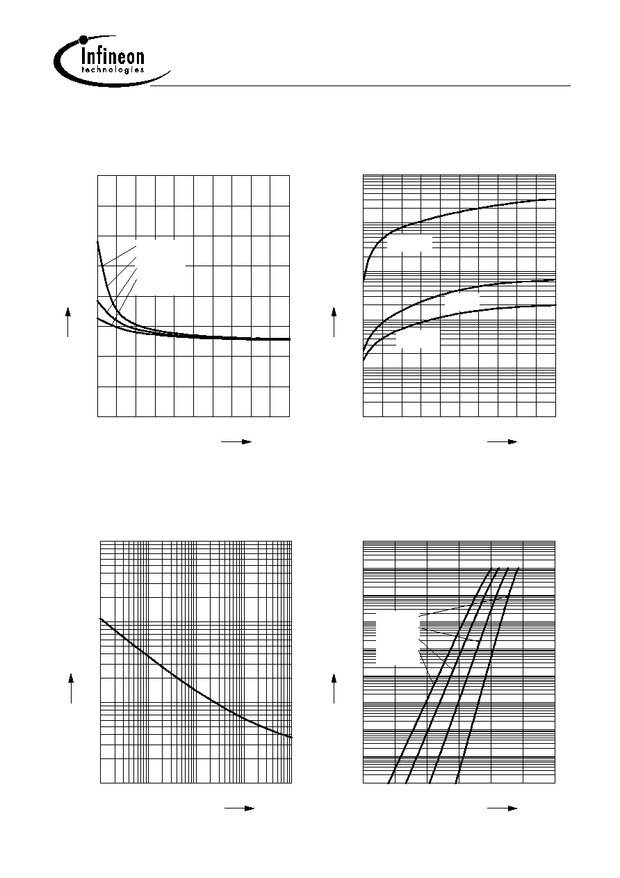
Diode capacitance
V
R
= 1 V, f = 1 MHz
V
R
= 0 V, f = 100 MHz
V
R
= 0 V, f = 1 GHz
V
R
= 0 V, f = 1.8 GHz
C
T
-
-
-
-
0.3
0.4
0.28
0.25
0.4
-
-
-
pF
Reverse parallel resistance
V
R
= 0 V, f = 100 MHz
V
R
= 0 V, f = 1 GHz
V
R
= 0 V, f = 1.8 GHz
R
P
-
-
-
65
2.5
1.5
-
-
-
k
Forward resistance
I
F
= 1 mA, f = 100 MHz
I
F
= 5 mA, f = 100 MHz
I
F
= 10 mA, f = 100 MHz
r
f
-
-
-
1.5
0.8
0.6
2.5
-
-
Charge carrier life time
I
F
= 10 mA, I
R
= 6 mA, measured at I
R
= 3 mA,
R
L
= 100
rr
-
500
-
ns
I-region width
W
I
-
13
-
µm
Insertion loss
1)
I
F
= 1 mA, f = 1.8 GHz
I
F
= 5 mA, f = 1.8 GHz
I
F
= 10 mA, f = 1.8 GHz
|S
21
|
2
-
-
-
-0.11
-0.07
-0.06
-
-
-
dB
Isolation
1)
V
R
= 0 V, f = 0.9 GHz
V
R
= 0 V, f = 1.8 GHz
V
R
= 0 V, f = 2.45 GHz
|S
21
|
2
-
-
-
-15
-11
-9
-
-
-
1
BAR88-02L in series configuration,
Z
= 50