Jun-15-2004
1
BAT60B...
Silicon Schottky Diode
∑
High current rectifier Schottky diode with
very low V
F
drop (typ. 0.24 V at I
F
= 10mA)
∑
For power supply applications
∑
For clamping and protection in
low voltage applications
∑
For detection and step-up-conversion
BAT60B
1
2
ESD
: Electrostatic discharge sensitive device, observe handling precaution!
Type
Package
Configuration
Marking
BAT60B
SOD323
single
white/5
Maximum Ratings
at T
A
= 25∞C, unless otherwise specified
Parameter
Symbol
Value
Unit
Diode reverse voltage
1)
V
R
10
V
Forward current
I
F
3
A
Non-repetitive peak surge forward current
(t
10ms)
I
FSM
5
Total power dissipation
T
S
28∞C
P
tot
1350
mW
Junction temperature
T
j
150
∞C
Operating temperature range
T
op
-55 ... 125
Storage temperature
T
stg
-55 ... 150
Thermal Resistance
Parameter
Symbol
Value
Unit
Junction - soldering point
2)
R
thJS
90
K/W
1
For T
A
> 25 ∞C the derating of V
R
has to be considered. Please refer to curve Permissible reverse voltage.
2
For calculation of R
thJA
please refer to Application Note Thermal Resistance

Jun-15-2004
2
BAT60B...
Electrical Characteristics
at T
A
= 25∞C, unless otherwise specified
Parameter
Symbol
Values
Unit
min.
typ.
max.
DC Characteristics
Reverse current
1)
V
R
= 5 V
V
R
= 8 V
V
R
= 5 V, T
A
= 80 ∞C
V
R
= 8 V, T
A
= 80 ∞C
I
R
-
-
-
-
5
10
100
410
15
25
800
1500
µA
Forward voltage
1)
I
F
= 10 mA
I
F
= 100 mA
I
F
= 500 mA
I
F
= 1000 mA
V
F
0.2
0.26
0.32
0.36
0.24
0.32
0.4
0.48
0.3
0.38
0.5
0.6
V
AC Characteristics
Diode capacitance
V
R
= 5 V, f = 1 MHz
C
T
12
25
30
pF
1
Pulsed test: t
p
= 300 µs; D = 0.01

Jun-15-2004
3
BAT60B...
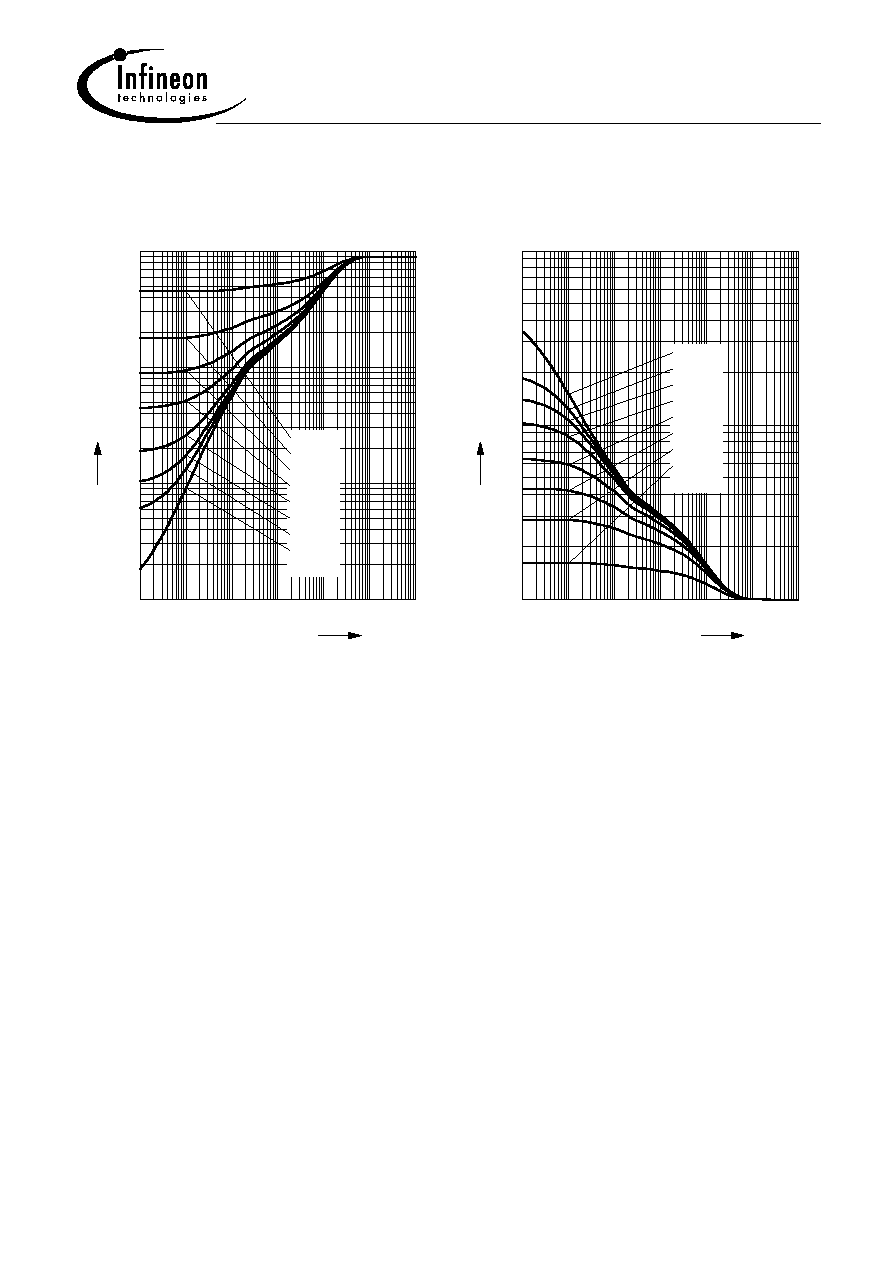
Reverse current
I
R
=
(V
R
)
T
A
= Parameter
0
2
4
6
8
V
12
V
R
-10
10
-9
10
-8
10
-7
10
-6
10
-5
10
-4
10
-3
10
-2
10
A
I
R
25∞C
-40∞C
85∞C
125∞C
Forward current
I
F
=
(V
F
)
T
A
= Parameter
0
0.1
0.2
0.3
0.4
0.5
0.6
V
0.8
VF
-5
10
-4
10
-3
10
-2
10
-1
10
0
10
A
IF
-40∞C
25∞C
85∞C
125∞C
Permissible Reverse voltage
V
R
=
(T
A
)
t
p
= Parameter; duty cycle < 0.01
Device mounted on PCB with Rth = 160 K/W
0
20
40
60
80
100
120 ∞C
150
T
A
0
1
2
3
4
5
6
7
8
9
10
V
12
V
R
300µs
100ms
DC
Forward current
I
F
=
(T
S
)
0
15
30
45
60
75
90 105 120 ∞C
150
T
S
0
500
1000
1500
2000
2500
mA
3500
I
F