
IA63484
Data Sheet
Advanced CRT Controller
Copyright
©
2001 ENG 21101041200 www.innovasic.com
innov
ASIC
Customer Support:
The End of Obsolescence
TM
Page
1
of
32
1-888-824-4184
FEATURES
∑
High-speed graphics
- Drawing rate: 200 ns/pixel max (color drawing)
- Commands: 38 commands including 23 graphic drawing commands:
Dot, Line, Rectangle, Poly-line, Polygon, Circle, Ellipse, Paint, Copy, etc.
- Colors: 16 bits/word: 1,2,4,8,16 bits/pixel (5 types) monochrome to 64k colors max
- Pattern RAM: 32 bytes
- Converts logical X-Y coordinate to physical address
- Color operation and conditional drawing
- Drawing area control for hardware clipping and hitting
∑
Large frame-memory space
- Maximum 2 Mbytes graphic memory and 128 kbytes character memory separate from
MPU memory.
- Maximum Resolution: 4096 x 4096 pixels (1 bit/pixel mode)
∑
CRT display control
- Split Screens: three displays and one window
-
Zoom: 1 to 16 times
-
Scroll: vertical and horizontal
∑
Interleaved access mode for flashless display and superimposition
∑
External synchronization between ARTCs or between ACRTC and external device (TV system
or other controller.
∑
DMA interface
∑
Two programmable cursors
∑
Three Scan modes
- Non-interlaced
- Interlace sync
- Interlace sync and video
∑
Interrupt request to MPU
∑
256 characters/line 32 raster/ line, 4096 rasters/screen
∑
Maximum clock frequency: 25MHz
∑
CMOS, single +5V power supply
The IA63484 is a "plug-and-play" drop-in replacement for the original Hitachi© HD63484. This
replacement IC has been developed using innovASIC's MILES
TM
, or Managed IC Lifetime
Extension System, cloning technology. This technology produces replacement ICs far more complex
than "emulation" while ensuring they are compatible with the original IC. MILES
TM
captures the
design of a clone so it can be produced even as silicon technology advances. MILES
TM
also verifies
the clone against the original IC so that even the "undocumented features" are duplicated. This data
sheet documents all necessary engineering information about the IA63484 including functional and
I/O descriptions, electrical characteristics, and applicable timing.
IA63484
Data Sheet
Advanced CRT Controller
Copyright
©
2001 ENG 21101041200 www.innovasic.com
innov
ASIC
Customer Support:
The End of Obsolescence
TM
Page
2
of
32
1-888-824-4184
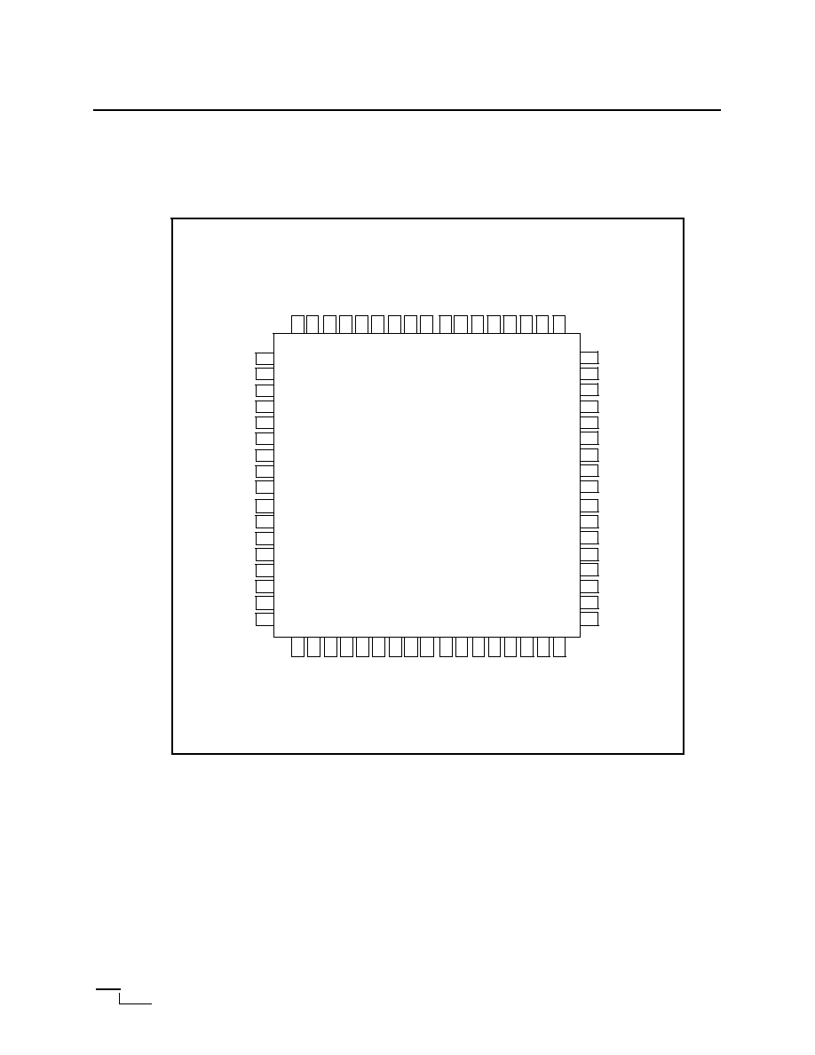
68 Pin Package: ACRTC PLCC PINOUT
Pin Arrangement:
mad10(T)
mad11(T)
done_n(O,D)
1
9
27
44
60
68
chr
mrd
draw_n
as_n
mcyc
Vss
Vss
clk_2
Vcc
mad5(T)
mad6(T)
mad7(T)
mad8(T)
mad9(T)
mad12(T)
mad13(T)
mad14(T)
mad15(T)
ma_ra16_0
ma_ra17_1
ma_ra18_2
ma_ra19_3
ra4
Vss
d15(T)
d14(T)
d13(T)
d12(T)
d11(T)
d10(T)
d9(T)
d8(T)
d7(T)
d6(T)
d5(T)
d4(T)
d3(T)
d2(T)
d1(T)
d0(T)
Vss
Vss
exsync_n
Vcc
vsync_n
hsync_n
irq(O,D)
dtack_n(T)
dack_n
mad4(T)
mad3(T)
mad2(T)
mad1(T)
mad0(T)
disp2_n
disp1_n
lpstb
Vcc
cud1_n
cud2_n
rw_n
cs_n
rs
res_n
dreq_n
O,D: Open Drain
T: Three State
IA63484

IA63484
Data Sheet
Advanced CRT Controller
Copyright
©
2001 ENG 21101041200 www.innovasic.com
innov
ASIC
Customer Support:
The End of Obsolescence
TM
Page
3
of
32
1-888-824-4184
BLOCK DIAGRAM
Figure 1: System Block Diagram
Figure 2 illustrates the ACRTC system environment. The following paragraphs will further describe
the system block diagram and design in more detail.
L
Vcc
ACRTC
DMAC
MPU
(8/16b)
SYSTEM
MEMORY
DOT SHIFTER
FRAME
BUFFER
2MB, MAX
CRT
Vss
clk_2
done_n
dack_n
dreq_n
rw_n
rs
cs_n
dtack_n
irq_n
res_n
disp1_n
cud1_n
lpstb
exsync_n
vsync_n
hsync_n
as_n
mrd
disp2_n
cud2_n
VIDEO
SIGNAL
CONTROL
DATA
ADDRESS
d[15:0]
ma[19:16]
mad[15:0]

IA63484
Data Sheet
Advanced CRT Controller
Copyright
©
2001 ENG 21101041200 www.innovasic.com
innov
ASIC
Customer Support:
The End of Obsolescence
TM
Page
4
of
32
1-888-824-4184
I/O SIGNAL DESCRIPTION:
The diagram below describes the I/O characteristics for each signal on the IC. The signal names
correspond to the signal names on the pinout diagrams provided.
I/O Characteristics:
Signal Name
I/O
Group
Description
res_n
I
ACRTC reset:
d[15,0]
I/O
Data bus (three state): are the bidirectional data bus to the host mpu or dmac. D
0
-D
are used in 8-bit data bus mode.
rw_n
I
Read/write strobe: controls the direction of host/ACRTC transformers.
cs_n
I
Chip Select: enables transfers between the host and the ACRTC.
rs
I
Register Select: selects the ACRTC register to be accessed. It is usually connected to
the least significant bit of the host address bus.
dtack_n
O
Data transfer acknowledge (three state): output provides asynchronous bus cycle
timing. It is compatible with the HD68000 mpu dtack output.
irq_n
O
Interrupt request (open drain): output generates interrupt service requests to the
host MPU.
dreq_n
I
DMA request: recieves DMA acknowledge timing from the host DMAC.
dack
I/O
DMA acknoledge:
done_n
I
DMA done: terminates DMA transfer. It is compatible with the HD68450 DMAC
DONE signal.
clk_2
I/O
ARTC clock: is the baasic operating clock, twice the frequency of the dot clock.
mad[15,0]
O
Multiplexed frame buffer address/data bus: are the multiplexed frame buffer
address/data bus.
as_n
O
Address strobe: output demultiplexes the address/data bus.
MA16
/R
0
-*
MA
19
/RA
3
O
Higer-order address bits/character screen rastar address:MA16/R0- MA19/RA3 are
the upper bits of the graphics screen ddress multiplexed with th lower bits of the
character screen raster address.
RA
4
O
Higer-order character screen rastar address bit: is the high bit of the character screen
raster address (up to 32 rasters.)
chr
O
Graphic or character screen access: output indicates whether a graphic or character
screen is being accessed.
mcyc
O
Frame buffer memory acess timing signal: is the frame buffer access timing output,
1/2 the frequency of clk_2.
mrd
O
Frame buffer memory read: output controls the frame buffer data bus direction.
draw_n
O
Draw/refresh signal: output differentiates between drawing and CRT displayrefresh
cycles.
disp1, disp2
O
Display enable: programmable display enable outputs can enable, disable, and blanck
logical screens.
cud1, cud2
Coursor Display: outputs provides cursor timing programmed by ACRTC parameters
such as cursor definition, cursor mode, cursor address, etc.
vsync_n
O
CRT vertical sync pulse: outputs the crt vertical synchronization pulse.
hsync_n
CRT horizontal sync pulse: outputs the crt horizontal synchronization pulse.
exsync_n
I/O
External sync:allows synchronization between multiple ACRTSs and other videro
signal generators.
lpstb
I
Lightpen strobe: is the lightpen input
MPU
Interface
DMAC
Interface
CRT
Interface
IA63484
Data Sheet
Advanced CRT Controller
Copyright
©
2001 ENG 21101041200 www.innovasic.com
innov
ASIC
Customer Support:
The End of Obsolescence
TM
Page
5
of
32
1-888-824-4184
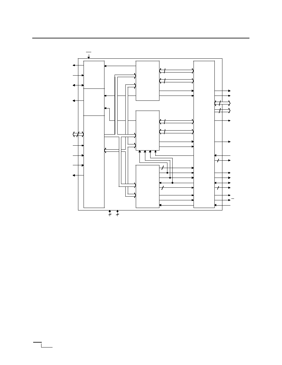
Figure 2: ACRTC Block Diagram
ACRTC System Description:
Some CRT controllers provide a single bus interface to the frame buffer that must be shared with the host
MPU. However, refreshing large frame buffers, and accessing the frame buffer for drawing operations can
quickly saturate the shared bus.
The ACRTC uses separate host MPU and frame buffer interfaces. This allows the ACRTC full access to the
frame buffer for display refresh and drawing operations and minimizes the use of the MPU system bus by the
ACRTC. A related benefit is that a large frame buffer (2 MB for each ACRTC) can be used, even if the host
MPU has a smaller address space or segment size restriction.
The ACRTC can use an external Direct Memory Access Controller (DMAC) to increase system throughput
when many commands, parameters and data must be transferred to the ACRTC. Advanced DMAC features
such as the HD68450 "chaining" modes can be used to develop powerful graphics system architectures.
More cost-sensitive or less performance-sensitive applications might not require a DMAC. In these cases, the
interface to the ACRTC can be handled under MPU software control.
While both ACRTC bus interfaces (host MPU and frame buffer) are 16 bits wide, the ACRTC also offers an
8 bit MPU mode for easy connection to popular 8 bit busses.
4
DMA
Control
Unit
Interrupt
Control
Unit
MPU
Interface
Drawing
Processor
Display
Processor
Timing
Processor
CRT
Interface
Register
Address
Data
20
16
draw_adrs[19:0]
draw_data[15:0]
draw_en
write
20
15
disp_adrs[19:0]
raster_adrs[4:0]
chr_int
ccud
gcud[1:0]
hsync
vsync
exsync
disp[1:0]
m_cyc
as
clk2
2
2
lpstb
16
2
hsync_n
vsync_n
exsync_n
disp1_n, disp2_n
mcyc
as_n
clk_2
d[15:0]
rs_n
rw_n
dtack_n
cs_n
irq_n
done_n
dack_n
dreq_n
res_n
lpstb
2
cud1_n, cud2_n
chr
mrd
draw_n
16
mad[15:0]
ma19_16_ra[3:0]
V
cc
23
V
SS
25
ra4