
MODELS
VDC O
UTPUT
B2-53
Size (max.): 3.200 x 2.600 x 0.460 inches (81.28 x 66.04 x 11.68 mm)
See Section B8, case N, for dimensions.
Weight:
120 grams typical
Screening: Standard or ES. See Section C2 for screening options,
see Section A5 for ordering information.
F
EATURES
∑ ≠55∞C to +125∞ C operation
∑ 16 TO 40 VDC input
∑ Four fully regulated outputs
∑ Internal EMI filter meets
MIL-STD-461C CE03
∑ Active transient suppressor
∑ Built in hold-up function with flag
∑ Fully isolated
∑ Magnetic feedback
∑ Fixed frequency, 550 kHz typical
∑ Topology ≠ Single Ended Forward
∑ Inhibit function
∑ Indefinite short circuit protection
∑ Undervoltage lockout
QUAD
±5 and ±12
±5 and ±15
DESCRIPTION
The MQO SeriesTM of DC/DC converters supply up to 16.5 watts in
a four output configuration of ±5 and ±12 or ±5 and ±15 VDC. An
integral EMI filter and transient suppressor allow the converters to
meet MIL-STD-461C standards without external components. An
output hold-up feature provides a low power flag and full output
power hold-up through transient dropout conditions.
The MQO Series converters are packaged in hermetically sealed
cases and are rated for full power operation from ≠55∞ to +125∞ C
case temperature. This makes these units ideal for military, aero-
space, and hi-rel industrial applications.
A high gain bandwidth magnetically isolated control loop is used to
precisely regulate the +5 VDC output. Constant frequency pulse
width with a single ended forward topology is used. The ≠5 VDC
output and the auxiliary outputs are independently controlled with
low headroom regulators, eliminating cross regulation errors. The
use of feedforward, compensation, and a high gain bandwidth
control loop provides excellent rejection to the conducted audio
spectrum of MIL-STD-704A-D and MIL-STD-461C.
I
NTEGRAL
EMI F
ILTER
The MQO Series includes a a built-in EMI filter and transient
suppressor which allow the units to meet the most common military
standards without any external components. The internal EMI filter
provides both differential and common mode attenuation on the
input power lines to allow meeting the CE03 interference and CS02
susceptibility requirements. The active internal transient suppressor
provides protection against MIL-STD-704A, 1275, and 461C line
transients. Protection is provided for transients up to 400 V from a
0.5 ohm source and 600 V from a 50 ohm source.
B
UILT
-I
N
H
OLD
-U
P
F
UNCTION WITH
F
LAG
An output hold-up feature provides a low power flag and full output
power hold-up through transient drop out conditions. At full load for
a Vin step from 28 to 0 volts, the minimum hold-up time will be 50
µs. The low power flag (TTL high) is asserted 10 µs before the end
of the hold-up time. External capacitance can be added to extend
hold-up time.
S
HORT
C
IRCUIT
P
ROTECTION
MQO Series converters provide predictable current limiters which
directly sense output load current in the converter's secondary.
During short circuit or overload conditions, the current limiters
provide constant output current and an input power fold-back.
U
NDERVOLTAGE
L
OCKOUT
Undervoltage lockout prevents the converters from operating below
approximately 12 VDC input voltage which helps keep system
current levels smooth, especially during initialization or re-start oper-
ations.
DC/DC C
ONVERTERS
28 V
OLT
I
NPUT
MQO SERIES
16 WATT

INHIBIT
TYPICAL CHARACTERISTICS
RECOMMENDED OPERATING CONDITIONS
ABSOLUTE MAXIMUM RATINGS
Input Voltage
∑ 16 to 40 V
Output Power
∑ 16.75 watts
Lead Soldering Temperature (10 sec per lead)
∑ 300∞C
Storage Temperature Range (Case)
∑ ≠65∞C to +150∞C
B2-54
MQO SERIES
16 WATT
DC/DC C
ONVERTERS
Undervoltage Lockout
∑ 12 V input typical
Isolation
∑ 100 megohm minimum at 500 V
Audio Rejection
∑ Up to 50 dB
Conversion Frequency
∑ 550 kHz typical
Input Voltage Range
∑ 16 to 40 VDC continuous
Case Operating Temperature (Tc)
∑ ≠55∞C to +125∞C full power
∑ ≠55∞C to +135∞C absolute
Derating Output Power/Current
∑ Linearly from 100% at 125∞C to 0% at 135∞C
Inhibit TTL Open Collector
∑ Logic low (output disabled)
∑ Referenced to input common
∑ Logic high (output enabled)
Open collector
MQO28512Q
MQO28515Q
PARAMETER
CONDITION
MIN TYP MAX
MIN
TYP
MAX
UNITS
OUTPUT VOLTAGE
+5
4.95
5.00
5.05
4.95
5.00
5.05
≠5
4.95
5.00
5.05
4.95
5.00
5.05
+ AUX.
11.90
12.00
12.10
14.90
15.00
15.10
VDC
≠ AUX.
11.90
12.00
12.10
14.90
15.00
15.10
OUTPUT CURRENT
+5
390
--
2000
390
--
2000
≠5
0
--
350
0
--
350
+ AUX.
0
--
208
0
--
167
mA
≠ AUX.
0
--
208
0
--
167
OUTPUT POWER
+5
1.95
--
10.00
1.95
--
10.00
V
IN
= 16 TO 40 VDC
≠5
0
--
1.75
0
--
1.75
+ AUX.
0
--
2.50
0
--
2.50
W
≠ AUX.
0
--
2.50
0
--
2.50
OUTPUT RIPPLE
+5
--
50
55
--
50
55
10 kHz to 2 MHz
≠5
--
--
30
--
--
30
+ AUX.
--
--
50
--
--
50
mV p-p
≠ AUX.
--
--
50
--
--
50
LINE REGULATION
V
IN
= 16 TO 36 VDC
+5
--
--
20
--
--
20
mV
≠5, ±AUX.
--
--
50
--
--
50
LOAD REGULATION
MINIMUM LOAD TO FULL ±5
--
20
120
--
20
120
mV
± AUX.
--
50
220 --
50
220
INPUT VOLTAGE
MINIMUM LOAD TO FULL
Tc = ≠55∞ TO +125∞ C
CONTINUOUS
16
28
40
16
28
40
VDC
TRANSIENT 50 ms
0.5 OHM SOURCE
--
--
400
--
--
400
50 OHM SOURCE
--
--
600
--
--
600
V
INPUT CURRENT
MINIMUM LOAD
--
--
230
--
--
230
FULL LOAD
--
--
960
--
--
960
mA
INHIBITED
--
--
10
--
--
10
INPUT RIPPLE --
50
--
--
50
--
mA p-p
EFFICIENCY
10 kHz TO 2 MHz
--
64
--
--
64
--
%
START-UP
DELAY
--
20
--
--
20
--
ms
Electrical Characteristics: 25∞C Tc, 28 VDC Vin, 100% load, unless otherwise specified.
MODEL NUMBERING KEY
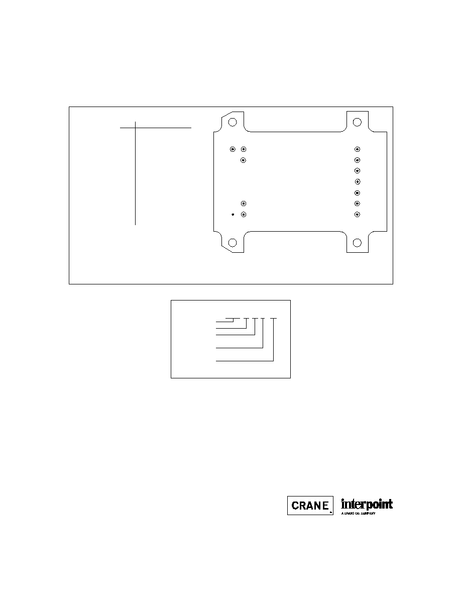
PIN OUT
B2-56
MQO SERIES
16 WATT
DC/DC C
ONVERTERS
Pin
Designation
1
Inhibit
2
Positive Input
3
Input Common
4
Positive 5 V Output
5
Output Common
6
Negative 5 V Output
7
Low Power Flag
8
Positive Aux.Output
9
Output Common
10
Negative Aux. Output
11
Hold-up Common
12
Positive Hold-up Input
13
Case Ground
1
2
3
11
12
13
4
5
6
7
8
9
10
BOTTOM VIEW
MQO
F
IGURE
2: P
IN
O
UT
MQO 28 512 Q / ES
Base Model
Input Voltage
Output Voltage
Number of Outputs
(Q = quad)
(Main and aux. Vout)
Screening
(Standard screening has no designator
in this position.)
See Section B8, case N, for dimensions
23624-001-DTS Rev A
DQ# 3003
All technical information is believed to be accurate, but no responsibility is
assumed for errors or omissions. Interpoint reserves the right to make changes in
products or specifications without notice. MQO Series is a trademark of Interpoint.
Copyright © 1991 - 1999 Interpoint. All rights reserved.

B8-34
CASE N
C
ASES
Materials
Header Cold Rolled Steel/Nickel/Tin
Cover
Cold Rolled Steel/Nickel/Tin
Pins
#52 alloy (all cases)
compression glass seal
Case dimensions in inches (mm)
Tolerance
±
0.005 (0.13) for three decimal places
±
0.01 (0.2) for two decimal places
unless otherwise specified
CAUTION
Heat from reflow or wave soldering may damage
the device. Solder pins individually with heat
application not exceeding 300
∞
C for 10 seconds
per pin.
2.600 max
(66.04)
3.200 max (81.28)
CASE N TOP VIEW
Cover Placement
and
Min/Max Dimensions
See Figure 53
for pin configuration
F
IGURE
52: C
ASE
N M
AXIMUM
D
IMENSIONS
