1
CAUTION: These devices are sensitive to electrostatic discharge; follow proper IC Handling Procedures.
http://www.intersil.com or 407-727-9207
|
Copyright
©
Intersil Corporation 1999
Ordering Information
PART NUMBER
TEMPERATURE RANGE
SCREENING LEVEL
PACKAGE
5962F9670601VEC
-55
o
C to +125
o
C
MIL-PRF-38535 Class V
16 Lead SBDIP
5962F9670601VXC
-55
o
C to +125
o
C
MIL-PRF-38535 Class V
16 Lead Ceramic Flatpack
ACS161D/Sample
25
o
C
Sample
16 Lead SBDIP
ACS161K/Sample
25
o
C
Sample
16 Lead Ceramic Flatpack
ACS161HMSR
25
o
C
Die
Die
ACS161MS
Radiation Hardened
4-Bit Synchronous Counter
January 1996
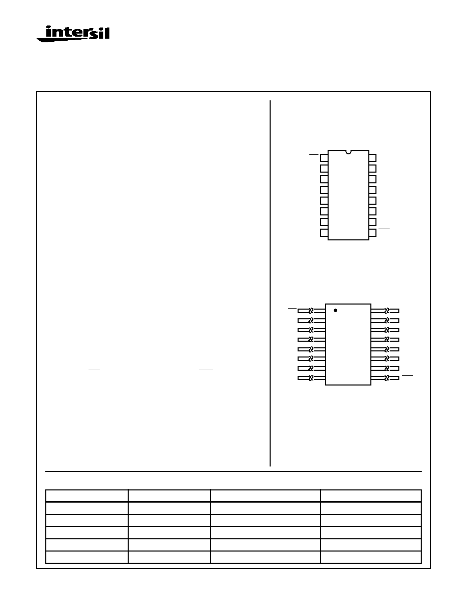
Pinouts
16 PIN CERAMIC DUAL-IN-LINE
MIL-STD-1835, DESIGNATOR CDIP2-T16,
LEAD FINISH C
TOP VIEW
16 PIN CERAMIC FLATPACK
MIL-STD-1835, DESIGNATOR CDFP4-F16,
LEAD FINISH C
TOP VIEW
14
15
16
9
13
12
11
10
1
2
3
4
5
7
6
8
CP
P0
P1
P2
P3
GND
PE
VCC
Q0
Q1
Q2
Q3
TE
SPE
TC
MR
2
3
4
5
6
7
8
1
16
15
14
13
12
11
10
9
MR
CP
P0
P1
P2
P3
PE
GND
VCC
TC
Q0
Q1
Q2
Q3
TE
SPE
Features
∑ Devices QML Qualified in Accordance with MIL-PRF-38535
∑ Detailed Electrical and Screening Requirements are Contained in
SMD# 5962-96706 and Intersil' QM Plan
∑ 1.25 Micron Radiation Hardened SOS CMOS
∑ Total Dose . . . . . . . . . . . . . . . . . . . . . . . . . . . . . . . . >300K RAD (Si)
∑ Single Event Upset (SEU) Immunity: <1 x 10
-10
Errors/Bit/Day
(Typ)
∑ SEU LET Threshold . . . . . . . . . . . . . . . . . . . . . . . >100 MEV-cm
2
/mg
∑ Dose Rate Upset . . . . . . . . . . . . . . . . >10
11
RAD (Si)/s, 20ns Pulse
∑ Dose Rate Survivability . . . . . . . . . . . >10
12
RAD (Si)/s, 20ns Pulse
∑ Latch-Up Free Under Any Conditions
∑ Military Temperature Range . . . . . . . . . . . . . . . . . . -55
o
C to +125
o
C
∑ Significant Power Reduction Compared to ALSTTL Logic
∑ DC Operating Voltage Range . . . . . . . . . . . . . . . . . . . . 4.5V to 5.5V
∑ Input Logic Levels
- VIL = 30% of VCC Max
- VIH = 70% of VCC Min
∑ Input Current
1
µ
A at VOL, VOH
∑ Fast Propagation Delay . . . . . . . . . . . . . . . . 21ns (Max), 14ns (Typ)
Description
The Intersil ACS161MS is a Radiation Hardened 4-Bit Binary Synchronous
Counter. The MR is an active low master reset. SPE is an active low
Synchronous Parallel Enable which disables counting and allows data at the
preset inputs (P0 - P3) to load the counter. CP is the positive edge clock. TC is
the terminal count or carry output. Both TE and PE must be high for counting
to occur, but are irrelevant to loading. TE low will keep TC low.
The ACS161MS utilizes advanced CMOS/SOS technology to achieve
high-speed operation. This device is a member of a radiation hardened,
high-speed, CMOS/SOS Logic family.
The ACS161MS is supplied in a 16 lead Ceramic Flatpack (K suffix) or a
Ceramic Dual-In-Line Package (D suffix).
Spec Number
518818
File Number
3600.1
2
ACS161MS
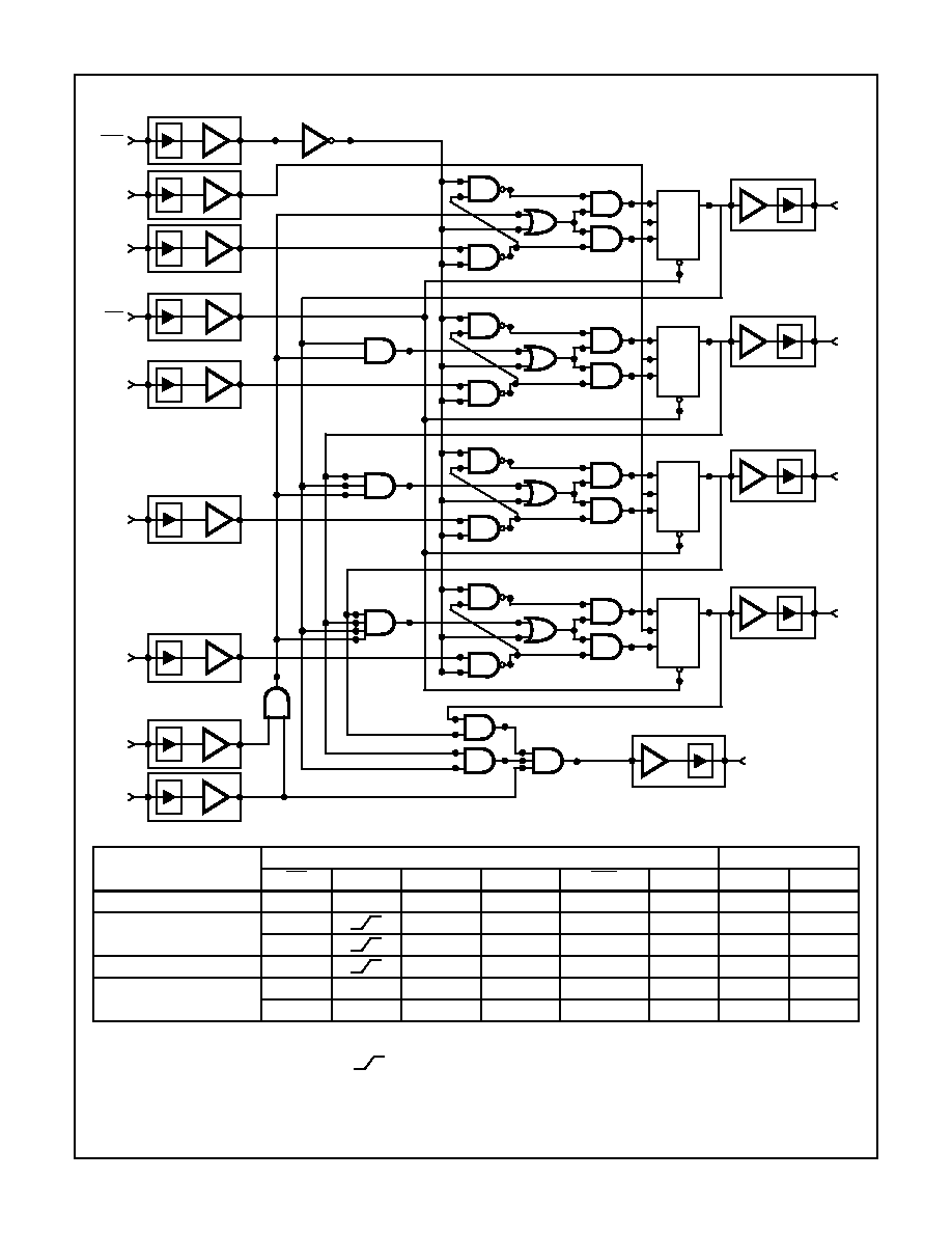
Functional Diagram
TRUTH TABLE
OPERATING MODE
INPUTS
OUTPUTS
MR
CP
PE
TE
SPE
P
N
Q
N
TC
Reset (Clear)
L
X
X
X
X
X
L
L
Parallel Load
H
X
X
I
I
L
L
H
X
X
I
h
H
(Note 1)
Count
H
h
h
h (Note 3)
X
count
(Note 1)
Inhibit
H
X
I (Note 2)
X
h (Note 3)
X
q
N
(Note 1)
H
X
X
I (Note 2)
h (Note 3)
X
q
N
L
H = High Steady State, L = Low Steady State, h = High voltage level one setup time prior to the Low-to-High clock transition, I = Low volt-
age level one setup time prior to the Low-to-High clock transition, X = Don't Care,q = Lower case letters indicate the state of the referenced
output prior to the Low-to-High clock transition,
= Low-to-High Transition.
NOTES:
1. The TC output is High when TE is High and the counter is at Terminal Count (HHHH).
2. The High-to-Low transition of PE or TE should only occur while ZCP is High for conventional operation.
3. The Low-to-High transition of SPE should only occur while CP is High for conventional operation.
4. The TC output is High when TE is High and the counter is at Terminal Count (HHHH).
CD
K
CP
J
Q
QN
CD
K
CP
J
Q
QN
CD
K
CP
J
Q
QN
CD
K
CP
J
Q
QN
SPE
CP
P0
MR
P1
P2
P3
PE
TE
Q3
TC
Q2
Q1
Q0
Spec Number
518818

4
All Intersil semiconductor products are manufactured, assembled and tested under ISO9000 quality systems certification.
Intersil products are sold by description only. Intersil Corporation reserves the right to make changes in circuit design and/or specifications at any time without
notice. Accordingly, the reader is cautioned to verify that data sheets are current before placing orders. Information furnished by Intersil is believed to be accurate
and reliable. However, no responsibility is assumed by Intersil or its subsidiaries for its use; nor for any infringements of patents or other rights of third parties which
may result from its use. No license is granted by implication or otherwise under any patent or patent rights of Intersil or its subsidiaries.
For information regarding Intersil Corporation and its products, see web site http://www.intersil.com
Sales Office Headquarters
NORTH AMERICA
Intersil Corporation
P. O. Box 883, Mail Stop 53-204
Melbourne, FL 32902
TEL: (407) 724-7000
FAX: (407) 724-7240
EUROPE
Intersil SA
Mercure Center
100, Rue de la Fusee
1130 Brussels, Belgium
TEL: (32) 2.724.2111
FAX: (32) 2.724.22.05
ASIA
Intersil (Taiwan) Ltd.
Taiwan Limited
7F-6, No. 101 Fu Hsing North Road
Taipei, Taiwan
Republic of China
TEL: (886) 2 2716 9310
FAX: (886) 2 2715 3029
ACS161MS
Spec Number
518818