 | –≠–ª–µ–∫—Ç—Ä–æ–Ω–Ω—ã–π –∫–æ–º–ø–æ–Ω–µ–Ω—Ç: CA3165E1 | –°–∫–∞—á–∞—Ç—å:  PDF PDF  ZIP ZIP |

CAUTION: These devices are sensitive to electrostatic discharge. Users should follow proper I.C. Handling Procedures.
Copyright
©
Harris Corporation 1999
10-25
[ /Title (CA3165)
/Subject (Electronic Switching Circuit)
/Author ()
/Keywords ()
/Creator ()
/DOCINFO pdfmark
[ /PageMode /UseOutlines
/DOCVIEW pdfmark
CA3165
Electronic Switching Circuit
Description
The CA3165 is a single chip electronic switching circuit
intended primarily for ignition applications. It includes an
oscillator that is amplitude-modulated by the rotor teeth of a
distributor, a detector that develops the positive going modu-
lation envelope, a Schmitt trigger that eliminates switching
uncertainties. Both types include two complementary high
current switched outputs for driving power transistors requir-
ing up to 120mA. The CA3165E also includes two comple-
mentary low current outputs that incorporate internal current
limiting and a non-inverting output amplifier with uncommit-
ted input capable of switching 27mA.
The CA3165 is supplied in the 8 lead dual-in-line plastic
package (E suffix) and in the 14 lead dual-in-line plastic
package (E1 suffix).
Features
∑ Switching Initiated by Damping of Internal Oscillator
∑ Proximity Sensing of Rotational Motion
∑ Repeatable Timing of Switching States
∑ Five Outputs - Two Complementary Pairs and One
Non-Inverting Output CA3165E1
∑ Two Outputs - One Complementary Pair CA3165E
Part Number Information
PART
NUMBER
TEMPERATURE
PACKAGE
CA3165E
-40
o
C to +85
o
C
8 Lead Plastic DIP
CA3165E1
-40
o
C to +85
o
C
14 Lead Plastic DIP
File Number
1278.3
May 1999
Pinouts
CA3165 (PDIP)
TOP VIEW
CA3165 (PDIP)
TOP VIEW
OSC FB
SENSE
GND
OUTPUT
1
2
3
4
8
7
6
5
FB_RF
V+
DET_OUT
INV_OUT
OSC FB
SENSE
GND
OUTPUT
+SIGNAL
INV_OUT
≠SIGNAL
NC
FB_R
F
V+
NC
DET_OUT
AMPL_IN
AMPL_OUT
1
2
3
4
5
6
7
14
13
12
11
10
9
8
OBSOLETE PRODUCT
NO RECOMMENDED REPLACEMENT
Call Central Applications 1-800-442-7747
or email: centapp@harris.com

10-26
CA3165
Functional Block Diagrams
FIGURE 1. FUNCTIONAL BLOCK DIAGRAM FOR CA3165E1
FIGURE 2. FUNCTIONAL BLOCK DIAGRAM FOR CA3165E
OSCILLATOR
CONDITION
TERMINAL 10
TERMINAL 4
TERMINAL 5
TERMINAL 6
TERMINAL 7
TERMINAL 8
Unloaded
Low
High
High
Low
Low
Low
Loaded
High
Low
Low
High
High
High
OSCILLATOR
CONDITION
TERMINAL 4
TERMINAL 5
TERMINAL 6
Unloaded
High
High
Low
Loaded
Low
Low
High
OSCILLATOR
DET
SCHMITT
TRIGGER
OUTPUT
OUTPUT
AMP
SWITCHING
FEEDBACK
RESISTOR
(6k
±
0.5%)
0.01
µ
F
13
1
2
220
L = 100
µ
H
Q
53
1500
pF
R
REPRESENTS
ROTOR LOADING
10
0.01
3
12
3.5V - 18V
220
DC SUPPLY 5V - 24V
NC
5
4
200
TO POWER
TRANSISTORS
847
0.01
µ
F
100K
0.0047
µ
F
6.8K
OUTPUT
8
9
7
6
OSCILLATOR
DET
SCHMITT
TRIGGER
OUTPUT
SWITCHING
FEEDBACK
RESISTOR
(6.49k
)
0.1
µ
F
8
1
2
220
L = 100
µ
H
Q
53
1500
pF
R
B
REPRESENTS
ROTOR LOADING
6
0.01
3
7
3.5V - 18V
220
DC SUPPLY 5V - 24V
4
200
TO POWER
TRANSISTORS
5
300
INVERTED
OUTPUT
R
A
VALUES OF R
A
AND R
B
DETERMINED
BY CORRELATION.
10-27
Specifications CA3165
Absolute Maximum Ratings
Thermal Information
DC Voltage (With Reference to Terminal 3)
CA3165E1
Terminals 4, 6, 8 . . . . . . . . . . . . . . . . . . . . . . . . . . . . . . . . . 24V
Terminals 5, 7, 12 . . . . . . . . . . . . . . . . . . . . . . . . . . . . . . . . 18V
Terminal 9 . . . . . . . . . . . . . . . . . . . . . . . . . . . . . . . . . . . . . . 1.5V
CA3165E
Terminals 4, 5 . . . . . . . . . . . . . . . . . . . . . . . . . . . . . . . . . . . 24V
Terminal 7 . . . . . . . . . . . . . . . . . . . . . . . . . . . . . . . . . . . . . . 18V
Current (At Terminals Indicated)
CA3165E1
Terminals 4, 6 . . . . . . . . . . . . . . . . . . . . . . . . . . . . . . . . . 120mA
Terminals 5, 7 . . . . . . . . . . . . . . . . . . . . . . . . . -0.1mA to 0.1mA
Terminal 8 . . . . . . . . . . . . . . . . . . . . . . . . . . . . . . . . . . . . . 30mA
CA3165E
Terminals 4, 5 . . . . . . . . . . . . . . . . . . . . . . . . . . . . . . . . . 120mA
Thermal Resistance
JA
Plastic DIP Package 8 Lead . . . . . . . . . . . . . . . . . . . . . 150
o
C/W
Plastic DIP Package 14 Lead . . . . . . . . . . . . . . . . . . . . 100
o
C/W
Operating Temperature Range . . . . . . . . . . . . . . . . . -40
o
C to +85
o
C
Storage Temperature Range. . . . . . . . . . . . . . . . . . -65
o
C to +150
o
C
Lead Temperature . . . . . . . . . . . . . . . . . . . . . . . . . . . . . . . . . +265
o
C
At Distance 1/16"
±
1/32" (1.59
±
0.79mm) from Case
for 10s Maximum
Device Dissipation Plastic DIP Package 8 Lead
Up to T
A
= +55
o
C. . . . . . . . . . . . . . . . . . . . . . . . . . . . . . . . 600mW
Above T
A
= +55
o
C . . . . . . . . . . . . . Derate Linearly at 6.67mW/
o
C
Device Dissipation Plastic DIP Package 14 Lead
Up to T
A
= +55
o
C. . . . . . . . . . . . . . . . . . . . . . . . . . . . . . . . 950mW
Above T
A
= +55
o
C . . . . . . . . . . . . . . .Derate Linearly at 10mW/
o
C
CAUTION: Stresses above those listed in "Absolute Maximum Ratings" may cause permanent damage to the device. This is a stress only rating and operation
of the device at these or any other conditions above those indicated in the operational sections of this specification is not implied.
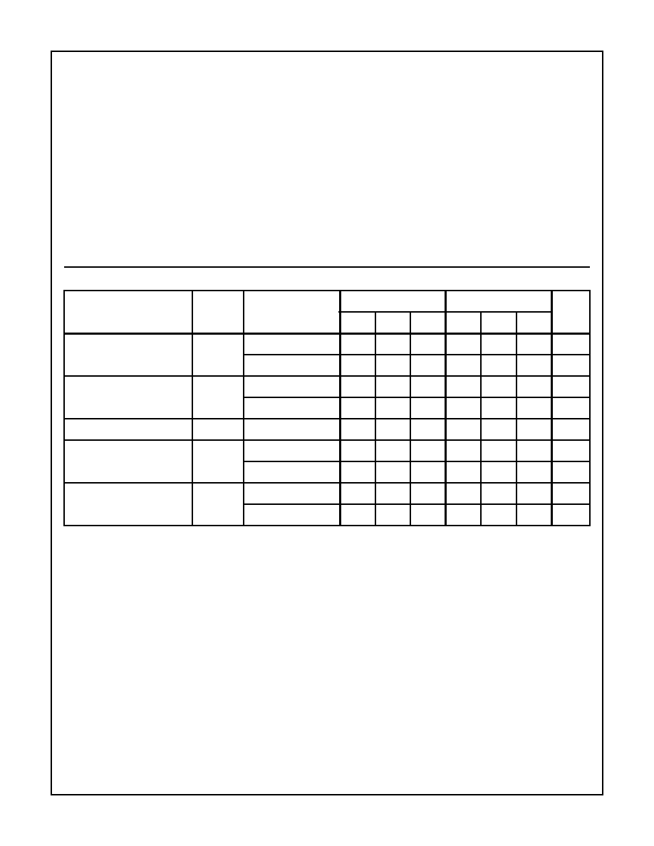
Electrical Specifications
At T
A
= +25
o
C, V+ = 13V, Measured in the circuit of Figure 5 (CA3165E1) or Figure 6 (CA3165E)
PARAMETERS
SYMBOL
TEST CONDITIONS
CA3165E1
CA3165E
UNITS
MIN
TYP
MAX
MIN
TYP
MAX
Input Current at Term. (Note 1)
Dwell
-
18.4
-
-
18.4
-
mA
Spark
-
17.5
-
-
17.5
-
mA
Output Voltage at Term. 4
V
4
Dwell
12.8
-
-
12.8
-
-
V
Spark
-
-
0.5
-
-
0.5
V
Output Volatge at Term. 7
V
7
Dwell
-
-
1
-
-
-
V
Output Voltage at Term. 8
V
8
Dwell
-
-
0.9
-
-
-
V
Portion of Spark
1.2
-
-
-
-
-
V
Oscillator Voltage at Term. 2
V
2
Dwell
-
4.4
-
-
4.4
-
Vp-p
Spark
-
0.6
-
-
0.6
-
Vp-p
NOTE:
1. CA3165E at Term. 7
CA3165E1 at Term. 12
I7
I12

10-28
CA3165
Schematic Diagrams
FIGURE 3. SCHEMATIC DIAGRAM FOR CA3165E1
FIGURE 4. SCHEMATIC DIAGRAM FOR CA3165E
9
8
7
6
5
4
10
2
1
13
Q16
12
3
R1
0.18
R2
0.18
R3
0.18
R4
0.18
R5
0.18
R17
10
R18
10
R20
4.3
R19
6.2
Q1
Q7
R10
0.35
Q11
R11
2.9
R12
1.8
Q2
Q3
Q4
Q5
Q6
R7
6.2
R6
0.6
R8
3.3
Q9
Q8
Q10
Q12
Q13
Q15
Q14
R13
2
R14
0.1
R15
1
Q17
R16
2.5
R9
3.3
R24
0.1
R29
0.05
Q27
Q18
Q19
Q20
Q21
Q22 Q23
Q28
Q29
R30
0.1
R
31
2
R32
5
R25
2.1
Q24
R27
1.8
R21
2.4
R23
5.1
R26 2.1
R28
2
Q25
Q26
Q30
R33
0.1
R34
2
R35
5
Q31
Q39
Q40
Q38
Q37
Q36
Q32
Q33
Q34
Q36
R37
4.5
ALL RESISTANCES ARE IN KILOHMS
R22
2.4
R36
4.6
1
7
Q6
Q1
Q2
Q3
Q4
Q5
Q7
Q8
Q15
Q33
Q16
Q17
Q18
Q19
Q20
Q29
Q31
Q30
Q40
Q41
Q32
Q22
Q24
Q23
Q25
Q26 Q28
Q27
Q35
Q36
Q37
Q14
Q39
Q13
Q10
Q12
Q11
Q9
Q21
Q38
R10
2.9
R12
1.8
R13
2
R13A
0.1
R15
1
R14
2.5
R11
0.35
R7
0.6
R6
6.2
R8
3.3
R9
3.3
R1
0.18
R2
0.18
R3
0.18
R4
0.18
R5
0.18
R17
10
R18
10
R19
10
R20
4.3
R21
2.4
R16
0.1
R15A
0.05
R25
2.1
R24A
1.8
R26
2.1
R22
2.4
R29
4.6
R30
4.5
R23
5.1
R24B
2
R31
0.1
R32
2
R27
5
R33
0.1
R34
2
R28
5
2
8
3
6
4
5
ALL RESISTANCES ARE IN KILOHMS
10-29
CA3165
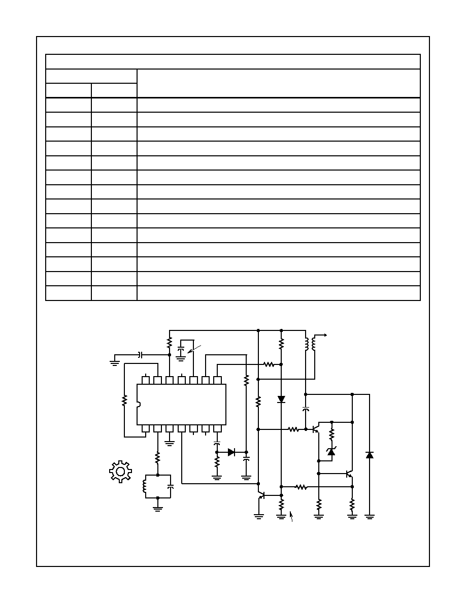
FIGURE 5. TYPICAL IGNITION SYSTEMS USING THE CA3165E1
Application Information
Figure 5 and Figure 6 show the application of the CA3165 in a typical ignition system.
TERMINAL DESCRIPTIONS
TERMINAL
FUNCTION
CA3165E1
CA3165E
1
1
Oscillator Feedback Resistor, R
F
2
2
220
Protective Resistor To Tank Circuit
3
3
Ground
4
4
Direct Output - R
7
load resistor 200
±
5%, and R
8
to power Darlington 15
±
10%
5
-
Direct Output - Low Current - Not Connected
6
5
Inverted High Current Output
7
-
Inverted Low Current Output Through C
1
(0.01
µ
F) to D
3
and R
3
(100k
)
8
-
Output Amplifier Output - Through R
6
and R
5
(27
and 820
to Supply)
9
-
Output Amplifier Input - through R
4
(6800
) to D
3
and C
5
(0.0047
µ
F)
10
6
Detector Output - C
2
to Ground (0.0
1µ
F)
11
-
No Connection
12
7
Circuit Supply Voltage Through R
1
(220
Protective Resistor) to Automotive Supply
13
8
Oscillator Feedback Resistor R
F
to Terminal 1
14
-
No Connection
R5
820
R6
27
R7
200
R4
6.8k
R3
100k
NC NC
C4
0.01
µ
F
C5
0.0047
µ
F
CURRENT
LIMITER
R9
6.8k
R8
15
NC
R1
220
C2
0.01
µ
F
C6
0.0047
µ
F
R12
100
R13
0.18
R11
1100
SET FOR 4 AMPERES IN R13
C1
0.01
µ
F
R
F
R2
220
C3
1500pF
L1
L1 SENSOR COIL INDUCTANCE
100
µ
H UNLOADED Q
53
METALLIC
TRIGGER WHEEL
ONE TOOTH PER
CYLINDER
AUTOMOTIVE SUPPLY 5V - 24V
NC
D3
D2
D4
D1
H.V.
1
2
3
4
5
6
7
14
13
12
11
10
9
8
CA3165E1 TOP VIEW
H.V.
R10
220
EXCEPT AS NOTED, RESISTOR VALUES IN OHMS