 | –≠–ª–µ–∫—Ç—Ä–æ–Ω–Ω—ã–π –∫–æ–º–ø–æ–Ω–µ–Ω—Ç: CP82C89 | –°–∫–∞—á–∞—Ç—å:  PDF PDF  ZIP ZIP |
4-343
March 1997
82C89
CMOS Bus Arbiter
Features
∑ Pin Compatible with Bipolar 8289
∑ Performance Compatible with:
- 80C86/80C88 . . . . . . . . . . . . . . . . . . . . . . . . . .(5/8MHz)
∑ Provides Multi-Master System Bus Control and
Arbitration
∑ Provides Simple Interface with 82C88/8288 Bus
Controller
∑ Synchronizes 80C86/8086, 80C88/8088 Processors
with Multi-Master Bus
∑ Bipolar Drive Capability
∑ Four Operating Modes for Flexible System Configura-
tion
∑ Low Power Operation
- ICCSB . . . . . . . . . . . . . . . . . . . . . . . . . . . . 10
µ
A (Max)
- ICCOP . . . . . . . . . . . . . . . . . . . . . . . . .1mA/MHz (Max)
∑ Operating Temperature Ranges
- C82C89 . . . . . . . . . . . . . . . . . . . . . . . . . .0
o
C to +70
o
C
- I82C89 . . . . . . . . . . . . . . . . . . . . . . . . . -40
o
C to +85
o
C
- M82C89 . . . . . . . . . . . . . . . . . . . . . . . -55
o
C to +125
o
C
Description
The Intersil 82C89 Bus Arbiter is manufactured using a self-
aligned silicon gate CMOS process (Scaled SAJI IV). This cir-
cuit, along with the 82C88 bus controller, provides full bus arbi-
tration and control for multi-processor systems. The 82C89 is
typically used in medium to large 80C86 or 80C88 systems
where access to the bus by several processors must be coordi-
nated. The 82C89 also provides high output current and capac-
itive drive to eliminate the need for additional bus buffering.
Static CMOS circuit design insures low operating power. The
advanced Intersil SAJI CMOS process results in perfor-
mance equal to or greater than existing equivalent products
at a significant power savings.
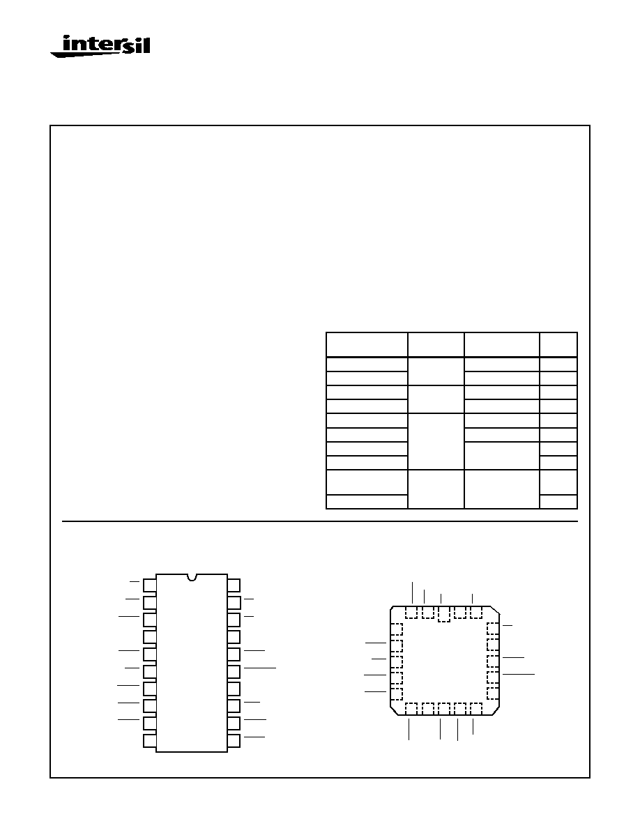
Pinouts
82C89 (CERDIP)
TOP VIEW
82C89 (PLCC, CLCC)
TOP VIEW
Ordering Information
PART NUMBER
PACKAGE
TEMPERATURE
RANGE
PKG.
NO.
CP82C89
20 Ld PDIP
0
o
C to +70
o
C
E20.3
IP82C89
-40
o
C to +85
o
C
E20.3
CS82C89
20 Ld PLCC
0
o
C to +70
o
C
N20.35
IS82C89
-40
o
C to +85
o
C
N20.35
CD82C89
20 Ld
CERDIP
0
o
C to +70
o
C
F20.3
ID82C89
-40
o
C to +85
o
C
F20.3
MD82C89/B
-55
o
C to +125
o
C
F20.3
5962-8552801RA
SMD#
F20.3
MR82C89/B
20 Pad
CLCC
-55
o
C to +125
o
C
J20.A
5962-85528012A
SMD#
J20.A
11
12
13
14
15
16
17
18
19
20
10
9
8
7
6
5
4
3
2
1
V
CC
CLK
ANYRQST
BUSY
CBRQ
AEN
CRQLCK
LOCK
S0
S1
GND
RESB
IOB
S2
BCLK
INIT
BREQ
BPRO
BPRN
SYSB/RESB
4
5
6
7
8
9
10
11
12
13
3
2
1
20
19
15
14
18
17
16
BCLK
RESB
INIT
BREQ
BPRO
GND
AEN
CBRQ
B
USY
BPRN
V
CC
IOB
S1
LOCK
CRQLCK
CLK
ANYRQST
S0
SYSB/
RESB
S2
File Number
2980.1
CAUTION: These devices are sensitive to electrostatic discharge; follow proper IC Handling Procedures.
http://www.intersil.com or 407-727-9207
|
Copyright
©
Intersil Corporation 1999

4-344
Functional Diagram
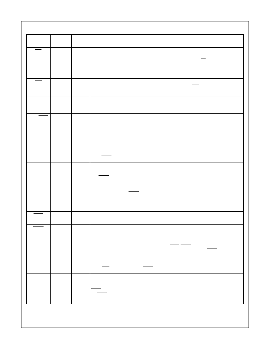
Pin Description
PIN
SYMBOL
NUMBER
TYPE
DESCRIPTION
V
CC
20
V
CC
: The +5V Power supply pin. A 0.1
µ
F capacitor between pins 10 and 20 is recommended for
decoupling.
GND
10
GROUND.
S0, S1, S2
1, 18-19
I
STATUS INPUT PINS: The status input pins from an 80C86, 80C88 or 8089 processor. The
82C89 decodes these pins to initiate bus request and surrender actions. (See Table 1).
CLK
17
I
CLOCK: From the 82C84A or 82C85 clock chip and serves to establish when bus arbiter actions
are initiated.
LOCK
16
I
LOCK: A processor generated signal which when activated (low) prevents the arbiter from surren-
dering the multi-master system bus to any other bus arbiter, regardless of its priority.
CRQLCK
15
I
COMMON REQUEST LOCK: An active low signal which prevents the arbiter from surrendering the
multi-master system bus to any other bus arbiter requesting the bus through the CBRQ input pin.
RESB
4
I
RESIDENT BUS: A strapping option to configure the arbiter to operate in systems having both a
multi-master system bus and a Resident Bus. Strapped high, the multi-master system bus is re-
quested or surrendered as a function of the SYSB/RESB input pin. Strapped low, the SYSB/RESB
input is ignored.
ANYRQST
14
I
ANY REQUEST: A strapping option which permits the multi-master system bus to be surrendered
to a lower priority arbiter as if it were an arbiter of higher priority (i.e., when a lower priority arbiter
requests the use of the multi-master system bus, the bus is surrendered as soon as it is possible).
When ANYRQST is strapped low, the bus is surrendered according to Table A in Design Informa-
tion. If ANYRQST is strapped high and CBRQ is activated, the bus is surrendered at the end of
the present bus cycle. Strapping CBRQ low and ANYRQST high forces the 82C89 arbiter to sur-
render the multi-master system bus after each transfer cycle. Note that when surrender occurs
BREQ is driven false (high).
CONTROL
ARBITRATION
MULTIBUS
INTERFACE
LOCAL
BUS
INTERFACE
+5V
GND
CONTROL/
STRAPPING
OPTIONS
80C86/
80C88
STATUS
COMMAND
SIGNALS
MULTIBUS
TM
SYSTEM
SIGNALS
MULTIBUS
TM
IS AN INTEL CORP. TRADEMARK
BPRN
SYSB/
RESB
INIT
BCLK
BREQ
BPRO
BUSY
CBRQ
AEN
CLK
RESB
ANYRQST
LOCK
S 1
IOB
CRQLCK
S 0
S 2
STATUS
DECODER
82C89
4-345
IOB
2
I
IO BUS: A strapping option which configures the 82C89 Arbiter to operate in systems having both
an IO Bus (Peripheral Bus) and a multi-master system bus. The arbiter requests and surrenders
the use of the multi-master system bus as a function of the status line, S2. The multi-master sys-
tem bus is permitted to be surrendered while the processor is performing IO commands and is
requested whenever the processor performs a memory command. Interrupt cycles are assumed
as coming from the peripheral bus and are treated as an IO command.
AEN
13
O
ADDRESS ENABLE: The output of the 82C89 Arbiter to the processor's address latches, to the
82C88 Bus Controller and 82C84A or 82C85 Clock Generator. AEN serves to instruct the Bus
Controller and address latches when to three-state their output drivers.
INIT
6
I
INITIALIZE: An active low multi-master system bus input signal used to reset all the bus arbiters
on the multi-master system bus. After initialization, no arbiters have the use of the multi-master
system bus.
SYSB/RESB
3
I
SYSTEM BUS/RESIDENT BUS: An input signal when the arbiter is configured in the System/Res-
ident Mode (RESB is strapped high) which determines when the multi-master system bus is re-
quested and multi-master system bus surrendering is permitted. The signal is intended to originate
from a form of address-mapping circuitry, such as a decoder or PROM attached to the resident
address bus. Signal transitions and glitches are permitted on this pin from
1 of T4 to
1 of T2 of
the processor cycle. During the period from
1 of T2 to
1 of T4, only clean transitions are permit-
ted on this pin (no glitches). If a glitch occurs, the arbiter may capture or miss it, and the multi-mas-
ter system bus may be requested or surrendered, depending upon the state of the glitch. The
arbiter requests the multi-master system bus in the System/Resident Mode when the state of the
SYSB/RESB pin is high and permits the bus to be surrendered when this pin is low.
CBRQ
12
I/O
COMMON BUS REQUEST: An input signal which instructs the arbiter if there are any other arbi-
ters of lower priority requesting the use of the multi-master system bus.
The CBRQ pins (open-drain output) of all the 82C89 Bus Arbiters which surrender to the multi-
master system bus upon request are connected together.
The Bus Arbiter running the current transfer cycle will not itself pull the CBRQ line low. Any other
arbiter connected to the CDRQ line can request the multi-master system bus. The arbiter presently
running the current transfer cycle drops its BREQ signal and surrenders the bus whenever the
proper surrender conditions exist. Strapping CBRQ low and ANYRQST high allows the multi-mas-
ter system bus to be surrendered after each transfer cycle. See the pin definition of ANYRQST.
BCLK
5
I
BUS CLOCK: The multi-master system bus clock to which all multi-master system bus interface
signals are synchronized.
BREQ
7
O
BUS REQUEST: An active low output signal in the Parallel Priority Resolving Scheme which the
arbiter activates to request the use of the multi-master system bus.
BPRN
9
I
BUS PRIORITY IN: The active low signal returned to the arbiter to instruct it that it may acquire the
multi-master system bus on the next falling edge of BCLK. BPRN active indicates to the arbiter that
it is the highest priority requesting arbiter presently on the bus. The loss of BPRN instructs the ar-
biter that it has lost priority to a higher priority arbiter.
BPRO
8
O
BUS PRIORITY OUT: An active low output signal used in the serial priority resolving scheme
where BPRO is daisy-chained to BPRN of the next lower priority arbiter.
BUSY
11
I/O
BUSY: An active low open-drain multi-master system bus interface signal used to instruct all the
arbiters on the bus when the multi-master system bus is available. When the multi-master system
bus is available the highest requesting arbiter (determined by BPRN) seizes the bus and pulls
BUSY low to keep other arbiters off of the bus. When the arbiter is done with the bus, it releases
the BUSY signal, permitting it to go high and thereby allowing another arbiter to acquire the multi-
master system bus.
Pin Description
(Continued)
PIN
SYMBOL
NUMBER
TYPE
DESCRIPTION
82C89
4-346
Functional Description
The 82C89 Bus Arbiter operates in conjunction with the
82C88 Bus Controller to interface 80C86, 80C88 processors
to a multi-master system bus (both the 80C86 and 80C88
are configured in their max mode). The processor is
unaware of the arbiter's existence and issues commands as
though it has exclusive use of the system bus. If the proces-
sor does not have the use of the multi-master system bus,
the arbiter prevents the Bus Controller (82C88), the data
transceivers and the address latches from accessing the
system bus (e.g. all bus driver outputs are forced into the
high impedance state). Since the command sequence was
not issued by the 82C88, the system bus will appear as "Not
Ready" and the processor will enter wait states. The proces-
sor will remain in Wait until the Bus Arbiter acquires the use
of the multi-master system bus whereupon the arbiter will
allow the bus controller, the data transceivers, and the
address latches to access the system. Typically, once the
command has been issued and a data transfer has taken
place, a transfer acknowledge (XACK) is returned to the pro-
cessor to indicate "READY" from the accessed slave device.
The processor then completes its transfer cycle. Thus the
arbiter serves to multiplex a processor (or bus master) onto
a multi-master system bus and avoid contention problems
between bus masters.
Arbitration Between Bus Masters
In general, higher priority masters obtain the bus when a
lower priority master completes its present transfer cycle.
Lower priority bus masters obtain the bus when a higher pri-
ority master is not accessing the system bus. A strapping
option (ANYRQST) is provided to allow the arbiter to surren-
der the bus to a lower priority master as though it were a
master of higher priority. If there are no other bus masters
requesting the bus, the arbiter maintains the bus so long as
its processor has not entered the HALT State. The arbiter will
not voluntarily surrender the system bus and has to be forced
off by another master's bus request, the HALT State being
the only exception. Additional strapping options permit other
modes of operation wherein the multi-master system bus is
surrendered or requested under different sets of conditions.
Priority Resolving Techniques
Since there can be many bus masters on a multi-master sys-
tem bus, some means of resolving priority between bus
masters simultaneously requesting the bus must be pro-
vided. The 82C89 Bus Arbiter provides several resolving
techniques. All the techniques are based on a priority con-
cept that at a given time one bus master will have priority
above all the rest. There are provisions for using parallel pri-
ority resolving techniques, serial priority resolving tech-
niques, and rotating priority techniques.
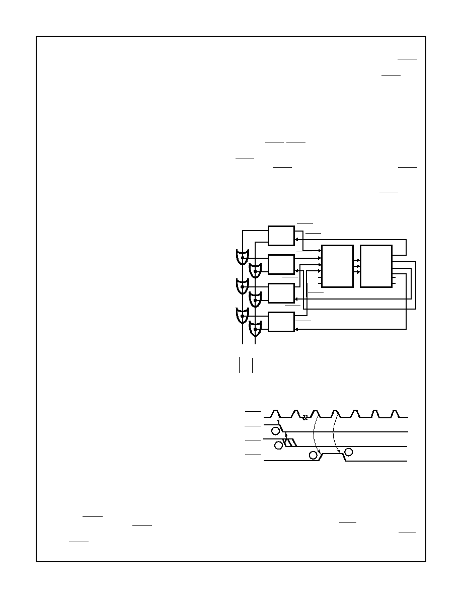
Parallel Priority Resolving
The parallel priority resolving technique uses a separate bus
request line BREQ for each arbiter on the multi-master sys-
tem bus, see Figure 1. Each BREQ line enters into a priority
encoder which generates the binary address of the highest
priority BREQ line which is active. The binary address is
decoded by a decoder to select the corresponding BPRN
(Bus Priority In) line to be returned to the highest priority
requesting arbiter. The arbiter receiving priority (BPRN true)
then allows its associated bus master onto the multi-master
system bus as soon as it becomes available (i.e., the bus is
no longer busy). When one bus arbiter gains priority over
another arbiter it cannot immediately seize the bus, it must
wait until the present bus transaction is complete. Upon
completing its transaction the present bus occupant recog-
nizes that it no longer has priority and surrenders the bus by
releasing BUSY. BUSY is an active low "OR" tied signal line
which goes to every bus arbiter on the system bus. When
BUSY goes inactive (high), the arbiter which presently has
bus priority (BPRN true) then seizes the bus and pulls BUSY
low to keep other arbiters off of the bus. See waveform tim-
ing diagram, Figure 2. Note that all multimaster system bus
transactions are synchronized to the bus clock (BCLK). This
allows the parallel priority resolving circuitry or any other pri-
ority resolving scheme employed to settle.
FIGURE 1. PARALLEL PRIORITY RESOLVING TECHNIQUE
FIGURE 2. HIGHER PRIORITY ARBITER OBTAINING THE BUS
FROM A LOWER PRIORITY ARBITER
NOTES:
1. Higher priority bus arbiter requests the Multi-Master system bus.
2. Attains priority.
3. Lower priority bus arbiter releases BUSY.
4. Higher priority bus arbiter then acquires the bus and pulls BUSY
down.
BUS
ARBITER
1
BUS
ARBITER
2
BUS
ARBITER
3
BUS
ARBITER
4
74HC148
PRIORITY
ENCODER
74HC138
3 TO 8
ENCODER
∑
∑
∑
∑
∑∑
∑∑
∑ ∑
∑ ∑
BREQ
BPRN
BREQ
BPRN
BREQ
BPRN
BREQ
BPRN
B
USY
CBRQ
BCLK
BREQ
BPRN
BUSY
1
2
3
4
82C89

4-347
Serial Priority Resolving
The serial priority resolving technique eliminates the need
for the priority encoder-decoder arrangement by daisychain-
ing the bus arbiters together, connecting the higher priority
bus arbiter's BPRO (Bus Priority Out) output to the BPRN of
the next lower priority. See Figure 3.
Rotating Priority Resolving
The rotating priority resolving technique is similar to that of
the parallel priority resolving technique except that priority is
dynamically re-assigned. The priority encoder is replaced by
a more complex circuit which rotates priority between
requesting arbiters thus allowing each arbiter an equal
chance to use the multi-master system bus, over time.
Which Priority Resolving Technique To Use
There are advantages and disadvantages for each of the
techniques described above. The rotating priority resolving
technique requires substantial external logic to implement
while the serial technique uses no external logic but can
accommodate only a limited number of bus arbiters before the
daisy-chain propagation delay exceeds the multimaster's sys-
tem bus clock (BCLK). The parallel priority resolving tech-
nique is in general a good compromise between the other two
techniques. It allows for many arbiters to be present on the
bus while not requiring too much logic to implement.
82C89 Modes Of Operation
There are two types of processors for which the 82C89 will
provide support: An Input/Output processor (i.e. an NMOS
8089 IOP) and the 80C86, 80C88. Consequently, there are
two basic operating modes in the 82C89 bus arbiter. One,
the IOB (I/O Peripheral Bus) mode, permits the processor
access to both an I/O Peripheral Bus and a multi-master sys-
tem bus. The second, the RESB (Resident Bus mode), per-
mits the processor to communicate over both a Resident
Bus and a multi-master system bus. An I/O Peripheral Bus is
a bus where all devices on that bus, including memory, are
treated as I/O devices and are addressed by I/O commands.
All memory commands are directed to another bus, the
multi-master system bus. A Resident Bus can issue both
memory and I/O commands, but it is a distinct and separate
bus from the multi-master system bus. The distinction is that
the Resident Bus has only one master, providing full avail-
ability and being dedicated to that one master.
The IOB strapping option configures the 82C89 Bus Arbiter
into the IOB mode and the strapping option RESB config-
ures it into the RESB mode. It might be noted at this point
that if both strapping options are strapped false, the arbiter
interfaces the processor to a multi-master system bus only
(see Figure 4). With both options strapped true, the arbiter
interfaces the processor to a multi-master system bus, a
Resident Bus, and an I/O Bus.
In the IOB mode, the processor communicates and controls
a host of peripherals over the Peripheral Bus. When the I/O
Processor needs to communicate with system memory, it
does so over the system memory bus. Figure 5 shows a pos-
sible I/O Processor system configuration.
The 80C86 and 80C88 processors can communicate with a
Resident Bus and a multi-master system bus. Two bus con-
trollers and only one Bus Arbiter would be needed in such a
configuration as shown in Figure 6. In such a system config-
uration the processor would have access to memory and
peripherals of both busses. Memory mapping techniques are
applied to select which bus is to be accessed. The
SYSB/RESB input on the arbiter serves to instruct the arbi-
ter as to whether or not the system bus is to be accessed.
The signal connected to SYSB/RESB also enables or dis-
ables commands from one of the bus controllers. A sum-
mary of the modes that the 82C89 has, along with its
response to its status lines inputs, is shown in Table 1.
BUS
ARBITER
1
BUS
ARBITER
2
BUS
ARBITER
3
BUS
ARBITER
4
∑
∑
∑
∑
BPRN
BUSY
CBRQ
∑
∑
BPRO
BPRO
BPRO
BPRO
BPRN
BPRN
BPRN
FIGURE 3. SERIAL PRIORITY RESOLVING
NOTE: The number of arbiters that may be daisy-chained together
in the serial priority resolving scheme is a function of BCLK and the
propagation delay from arbiter to arbiter. Normally, at 10MHz only 3
arbiters may be daisychained.
82C89