 | –≠–ª–µ–∫—Ç—Ä–æ–Ω–Ω—ã–π –∫–æ–º–ø–æ–Ω–µ–Ω—Ç: EL5102IS | –°–∫–∞—á–∞—Ç—å:  PDF PDF  ZIP ZIP |
1
Æ
FN7331.2
CAUTION: These devices are sensitive to electrostatic discharge; follow proper IC Handling Procedures.
1-888-INTERSIL or 321-724-7143
|
Intersil (and design) is a registered trademark of Intersil Americas Inc.
Copyright © Intersil Americas Inc. 2002-2004. All Rights Reserved.
All other trademarks mentioned are the property of their respective owners.
P R E L I M I N A R Y
EL5102, EL5103, EL5202, EL5203, EL5302
400MHz Slew Enhanced VFAs
The EL5x02 and EL5x03 families represent high-speed
VFAs based on a CFA amplifier architecture. This gives the
typical high slew rate benefits of a CFA family along with the
stability and ease of use associated with the VFA type
architecture. With slew rates of 3500V/µs this family of
devices enables the use of voltage feedback amplifiers in a
space where the only alternative has been current feedback
amplifiers. This family will also be available in single, dual,
and triple versions, with 200MHz, 400MHz, and 750MHz
versions. These are all available in single, dual, and triple
versions.
Both families operate on single 5V or ±5V supplies from
minimum supply current. EL5x02 also features an output
enable function, which can be used to put the output in to a
high-impedance mode. This enables the outputs of multiple
amplifiers to be tied together for use in multiplexing
applications.
Typical applications for these families will include cable
driving, filtering, A-to-D and D-to-A buffering, multiplexing
and summing within video, communications, and
instrumentation designs.
Features
∑ Operates off 3V, 5V, or ±5V applications
∑ Power-down to 0µA (EL5x02)
∑ -3dB bandwidth = 400MHz
∑ ±0.1dB bandwidth = 50MHz
∑ Low supply current = 5mA
∑ Slew rate = 3500V/µs
∑ Low offset voltage = 5mV max
∑ Output current = 140mA
∑ A
VOL
= 2000
∑ Diff gain/phase = 0.01%/0.01∞
Applications
∑ Video amplifiers
∑ PCMCIA applications
∑ A/D drivers
∑ Line drivers
∑ Portable computers
∑ High speed communications
∑ RGB applications
∑ Broadcast equipment
∑ Active filtering
Ordering Information
PART
NUMBER
PACKAGE
TAPE & REEL
PKG. DWG. #
PART
NUMBER
PACKAGE
TAPE & REEL
PKG. DWG. #
EL5102IS
8-Pin SO
-
MDP0027
EL5202IY-T13
10-Pin MSOP
13"
MDP0043
EL5102IS-T7
8-Pin SO
7"
MDP0027
EL5203IS
8-Pin SO
-
MDP0027
EL5102IS-T13
8-Pin SO
13"
MDP0027
EL5203IS-T7
8-Pin SO
7"
MDP0027
EL5102IW-T7
6-Pin SOT-23
7" (3K pcs)
MDP0038
EL5203IS-T13
8-Pin SO
13"
MDP0027
EL5102IW-T7A
6-Pin SOT-23
7" (250 pcs)
MDP0038
EL5203IY
8-Pin MSOP
-
MDP0043
EL5103IC-T7
5-Pin SC-70
7" (3K pcs)
P5.049
EL5203IY-T7
8-Pin MSOP
7"
MDP0043
EL5103IC-T7A
5-Pin SC-70
7" (250 pcs)
P5.049
EL5203IY-T13
8-Pin MSOP
13"
MDP0043
EL5103IW-T7
5-Pin SOT-23
7" (3K pcs)
MDP0038
EL5302IU
16-Pin QSOP
-
MDP0040
EL5103IW-T7A
5-Pin SOT-23
7" (250 pcs)
MDP0038
EL5302IU-T7
16-Pin QSOP
7"
MDP0040
EL5202IY
10-Pin MSOP
-
MDP0043
EL5302IU-T13
16-Pin QSOP
13"
MDP0040
EL5202IY-T7
10-Pin MSOP
7"
MDP0043
Data Sheet
December 14, 2004
2
FN7331.2
December 14, 2004
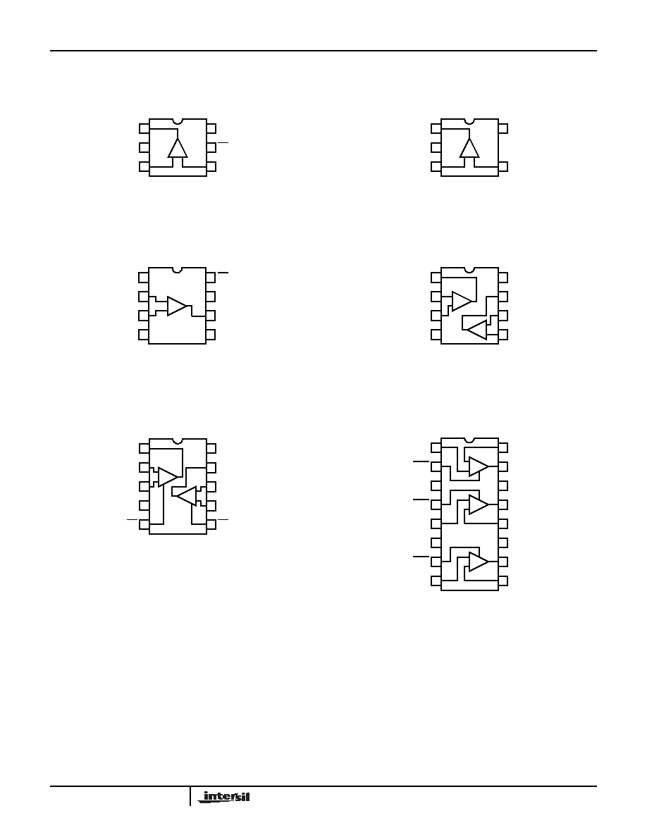
Pinouts
EL5102
(6-PIN SOT-23)
TOP VIEW
EL5103
(5-PIN SOT-23)
TOP VIEW
EL5102
(8-PIN SO)
TOP VIEW
EL5203
(8-PIN SO, MSOP)
TOP VIEW
EL5202
(10-PIN MSOP)
TOP VIEW
EL5302
(16-PIN QSOP)
TOP VIEW
1
2
3
6
4
5
+ -
OUT
VS-
IN+
VS+
CE
IN-
VS+
OUT
IN-
IN+
VS-
1
2
3
5
4
-
+
1
2
3
4
8
7
6
5
-
+
CE
VS+
OUT
NC
NC
IN-
IN+
VS-
1
2
3
4
8
7
6
5
-
+
-
+
OUTA
INA-
INA+
VS-
VS+
OUTB
INB-
INB+
1
2
3
4
10
9
8
7
5
6
OUT
IN-
IN+
VS-
VS+
OUT
IN-
IN+
CE
CE
-
+
7
-
+
1
2
3
4
16
15
14
13
5
6
7
12
11
10
8
9
-
+
-
+
-
+
INA+
CEA
VS-
CEB
INA-
OUTA
VS+
OUTB
INB+
NC
CEC
INC+
INB-
NC
OUTC
INC-
EL5102, EL5103, EL5202, EL5203, EL5302

3
FN7331.2
December 14, 2004
Absolute Maximum Ratings
(T
A
= 25∞C)
Supply Voltage between V
S
+ and GND. . . . . . . . . . . . . . . . . . 13.2V
Input Voltage . . . . . . . . . . . . . . . . . . . . . . . . . . . . . . . . . . . . . . . ±V
S
Differential Input Voltage . . . . . . . . . . . . . . . . . . . . . . . . . . . . . . .±4V
Maximum Continuos Output Current . . . . . . . . . . . . . . . . . . . . 80mA
Maximum Current into I
N
+, I
N
-, CE . . . . . . . . . . . . . . . . . . . . . ±5mA
Power Dissipation . . . . . . . . . . . . . . . . . . . . . . . . . . . . . See Curves
Storage Temperature Range . . . . . . . . . . . . . . . . . . -65∞C to +150∞C
Ambient Operating Temperature Range . . . . . . . . . . -40∞C to +85∞C
Operating Junction Temperature . . . . . . . . . . . . . . . . . . . . . . . 150∞C
CAUTION: Stresses above those listed in "Absolute Maximum Ratings" may cause permanent damage to the device. This is a stress only rating and operation of the
device at these or any other conditions above those indicated in the operational sections of this specification is not implied.
IMPORTANT NOTE: All parameters having Min/Max specifications are guaranteed. Typical values are for information purposes only. Unless otherwise noted, all tests
are at the specified temperature and are pulsed tests, therefore: T
J
= T
C
= T
A
DC Electrical Specifications
V
S
+
= +5V, V
S
-
= -5V, T
A
= 25∞C, R
L
= 150
, V
ENABLE
= +5V, unless otherwise specified.
PARAMETER
DESCRIPTION
CONDITIONS
MIN
TYP
MAX
UNIT
V
OS
Offset Voltage
EL5102, EL5103, EL5202, EL5203
1
5
mV
EL5302
2
8
mV
TCV
OS
Offset Voltage Temperature Coefficient
Measured from T
MIN
to T
MAX
10
µV/∞C
IB
Input Bias Current
V
IN
= 0V
-12
2
12
µA
I
OS
Input Offset Current
V
IN
= 0V
-8
1
8
µA
TCI
OS
Input Bias Current Temperature
Coefficient
Measured from T
MIN
to T
MAX
50
nA/∞C
PSRR
Power Supply Rejection Ratio
V
S
= ±4.75V to ±5.25V
-70
-80
dB
CMRR
Common Mode Rejection Ratio
V
CM
= -3V to 3.0V
-60
-80
dB
CMIR
Common Mode Input Range
Guaranteed by CMRR test
-3
±3.3
3
V
R
IN
Input Resistance
Common mode
200
400
k
C
IN
Input Capacitance
SO package
1
pF
I
S,ON
Supply Current - Enabled per amplifier
4.6
5.2
5.8
mA
I
S,OFF
Supply Current - Shut-down per amplifier V
S
+
+1
0
+25
µA
V
S
-
-25
7
-1
µA
AVOL
Open Loop Gain
V
OUT
= ±2.5V, R
L
= 1k
to GND
58
66
dB
V
OUT
= ±2.5V, R
L
= 150
to GND
60
dB
V
OUT
Output Voltage Swing
R
L
= 1k
to GND
±3.5
±3.9
V
R
L
= 150
to GND
±3.4
±3.7
V
I
OUT
Output Current
A
V
= 1, R
L
= 10
to 0V
±80
±150
mA
V
CE
-ON
CE Pin Voltage for Power-up
(V
S
+)-5
(V
S
+)-3
V
V
CE
-OFF
CE Pin Voltage for Shut-down
(V
S
+)-1
V
S
+
V
I
EN
-ON
Pin Current - Enabled
CE = 0V
-1
0
+1
µA
I
EN
-OFF
Pin Current - Disabled
CE = +5V
1
14
25
µA
EL5102, EL5103, EL5202, EL5203, EL5302

4
FN7331.2
December 14, 2004
Closed Loop AC Electrical Specifications
V
S
+
= +5V, V
S
-
= -5V, T
A
= 25∞C, V
ENABLE
= +5V, A
V
= +1, R
F
= 0
, R
L
= 150
to GND
pin, unless otherwise specified. (Note 1)
PARAMETER
DESCRIPTION
CONDITIONS
MIN
TYP
MAX
UNIT
BW
-3dB Bandwidth (V
OUT
= 400mV
P-P
)
A
V
= 1, R
F
= 0
400
MHz
SR
Slew Rate
A
V
= +2, R
L
= 100
, V
OUT
= -3V to +3V
1100
2200
5000
V/µs
R
L
= 500
, V
OUT
= -3V to +3V
4000
V/µs
t
R
,t
F
Rise Time, Fall Time
±0.1V step
2.8
ns
OS
Overshoot
±0.1V step
10
%
t
S
0.1% Settling Time
V
S
= ±5V, R
L
= 500
, A
V
= 1, V
OUT
= ±3V
20
ns
dG
Differential Gain (Note 2)
A
V
= 2, R
F
= 1k
0.01
%
dP
Differential Phase (Note 2)
A
V
= 2, R
F
= 1k
0.01
∞
e
N
Input Noise Voltage
f = 10kHz
6
nV/
Hz
i
N
Input Noise Current
f = 10kHz
1.25
pA/
Hz
t
DIS
Disable Time (Note 3)
50
ns
t
EN
Enable Time (Note 3)
25
ns
NOTES:
1. All AC tests are performed on a "warmed up" part, except slew rate, which is pulse tested.
2. Standard NTSC signal = 286mV
P-P
, f = 3.58MHz, as V
IN
is swept from 0.6V to 1.314V.R
L
is DC coupled.
3. Disable/Enable time is defined as the time from when the logic signal is applied to the ENABLE pin to when the supply current has reached half
its final value.
Typical Performance Curves
FIGURE 1. OPEN LOOP GAIN AND PHASE vs FREQUENCY
FIGURE 2. GAIN vs FREQUENCY FOR VARIOUS R
L
FREQUENCY (Hz)
GAI
N
(
d
B)
PHASE
(∞
)
10
100
1K
10K 100K 1M
10M 100M 1G
80
70
60
50
40
30
20
10
0
-10
-20
-45
0
45
90
135
180
225
270
315
360
405
V
CC
=+5V
V
EE
=-5V
NORM
ALIZE
D
GAI
N
(dB)
4
2
0
-2
-4
5
3
1
-1
-3
100K
1M
10M
700M
FREQUENCY (Hz)
100M
-5
A
V
=+1
C
L
=2.2pF
200
100
10
500
50
EL5102, EL5103, EL5202, EL5203, EL5302

5
FN7331.2
December 14, 2004
FIGURE 3. GAIN vs FREQUENCY FOR VARIOUS R
L
FIGURE 4.
GAIN vs FREQUENCY FOR VARIOUS R
L
FIGURE 5.
GAIN vs FREQUENCY FOR VARIOUS C
L
FIGURE 6.
GAIN vs FREQUENCY FOR VARIOUS C
L
FIGURE 7.
GAIN vs FREQUENCY FOR VARIOUS C
L
FIGURE 8. GAIN vs FREQUENCY FOR VARIOUS C
IN
-
Typical Performance Curves
(Continued)
NORM
ALIZE
D
GAIN (dB)
4
2
0
-2
-4
5
3
1
-1
-3
100K
1M
10M
700M
FREQUENCY (Hz)
100M
-5
A
V
=+2
C
L
=2.5pF
R
G
=270
10
500
150
50
NORM
ALIZE
D
GAIN (dB)
4
2
0
-2
-4
5
3
1
-1
-3
100K
1M
10M
FREQUENCY (Hz)
100M
-5
1.5k
500
150
50
10
A
V
=+5
C
L
=2.5pF
R
G
=270
NO
RM
ALIZED GAIN
(
d
B)
5
3
1
-1
-3
-5
100K
1M
100M
1G
FREQUENCY (Hz)
10M
4
2
0
-2
-4
A
V
=+1
R
L
=500
27pF
18pF
12pF
5.6pF
2.2pF
NORMALIZE
D
GAIN (dB)
4
2
0
-2
-4
100K
1M
100M 200M
FREQUENCY (Hz)
10M
3
1
-1
-3
-5
33pF
5
27pF
18pF
8.2pF
2.2pF
A
V
=+2
R
L
=500
R
G
=270
NORM
ALIZE
D
GAIN
(dB)
4
2
0
-2
-4
5
3
1
-1
-3
100K
1M
10M
FREQUENCY (Hz)
100M
-5
168pF
A
V
=+5
R
L
=500
R
G
=270
112pF
56pF
27pF
18pF
2.2pF
NORM
ALIZE
D
GAIN (dB)
4
2
0
-2
-4
5
3
1
-1
-3
100K
1M
10M
500M
FREQUENCY (Hz)
100M
A
V
=+2
R
L
=500
C
L
=2.2pF
R
G
=270
3.9pF
2.2pF
0pF
EL5102, EL5103, EL5202, EL5203, EL5302