1
Æ
FN7282.1
EL7202, EL7212, EL7222
High Speed, Dual Channel Power MOSFET
Drivers
The EL7202/EL7212/EL7222 ICs are matched dual-drivers
that improve the operation of the industry standard DS0026
clock drivers. The Elantec versions are very high speed
drivers capable of delivering peak currents of 2.0 amps into
highly capacitive loads. The high speed performance is
achieved by means of a proprietary "Turbo-Driver" circuit that
speeds up input stages by tapping the wider voltage swing at
the output. Improved speed and drive capability are
enhanced by matched rise and fall delay times. These
matched delays maintain the integrity of input-to-output
pulse-widths to reduce timing errors and clock skew
problems. This improved performance is accompanied by a
10 fold reduction in supply currents over bipolar drivers, yet
without the delay time problems commonly associated with
CMOS devices. Dynamic switching losses are minimized
with non-overlapped drive techniques.
Pinouts
Features
∑ Industry standard driver replacement
∑ Improved response times
∑ Matched rise and fall times
∑ Reduced clock skew
∑ Low output impedance
∑ Low input capacitance
∑ High noise immunity
∑ Improved clocking rate
∑ Low supply current
∑ Wide operating voltage range
∑
Pb-Free available (RoHS compliant)
Applications
∑ Clock/line drivers
∑ CCD Drivers
∑ Ultra-sound transducer drivers
∑ Power MOSFET drivers
∑ Switch mode power supplies
∑ Class D switching amplifiers
∑ Ultrasonic and RF generators
∑ Pulsed circuits
EL7212
(8-PIN PDIP, SO)
TOP VIEW
EL7222
(8-PIN PDIP, SO)
TOP VIEW
Inverting Drivers
Complementary Drivers
EL7202
(8-PIN PDIP, SO)
TOP VIEW
Non-Inverting Drivers
Manufactured under U.S. Patent Nos. 5,334,883, #5,341,047
Data Sheet
May 9, 2005
CAUTION: These devices are sensitive to electrostatic discharge; follow proper IC Handling Procedures.
1-888-INTERSIL or 1-888-352-6832
|
Intersil (and design) is a registered trademark of Intersil Americas Inc.
Copyright Intersil Americas Inc. 2003, 2005. All Rights Reserved
All other trademarks mentioned are the property of their respective owners.
3
Absolute Maximum Ratings
(T
A
= 25∞C)
Supply (V+ to Gnd) . . . . . . . . . . . . . . . . . . . . . . . . . . . . . . . . . 16.5V
Input Pins . . . . . . . . . . . . . . . . . . . . . . . . . . -0.3V to +0.3V above V+
Combined Peak Output Current. . . . . . . . . . . . . . . . . . . . . . . . . . .4A
Storage Temperature Range . . . . . . . . . . . . . . . . . .-65∞C to +150∞C
Ambient Operating Temperature . . . . . . . . . . . . . . . .-40∞C to +85∞C
Operating Junction Temperature . . . . . . . . . . . . . . . . . . . . . . . 125∞C
Power Dissipation
SOIC . . . . . . . . . . . . . . . . . . . . . . . . . . . . . . . . . . . . . . 570mW
PDIP . . . . . . . . . . . . . . . . . . . . . . . . . . . . . . . . . . . . . 1050mW
CAUTION: Stresses above those listed in "Absolute Maximum Ratings" may cause permanent damage to the device. This is a stress only rating and operation of the
device at these or any other conditions above those indicated in the operational sections of this specification is not implied.
IMPORTANT NOTE: All parameters having Min/Max specifications are guaranteed. Typical values are for information purposes only. Unless otherwise noted, all tests
are at the specified temperature and are pulsed tests, therefore: T
J
= T
C
= T
A
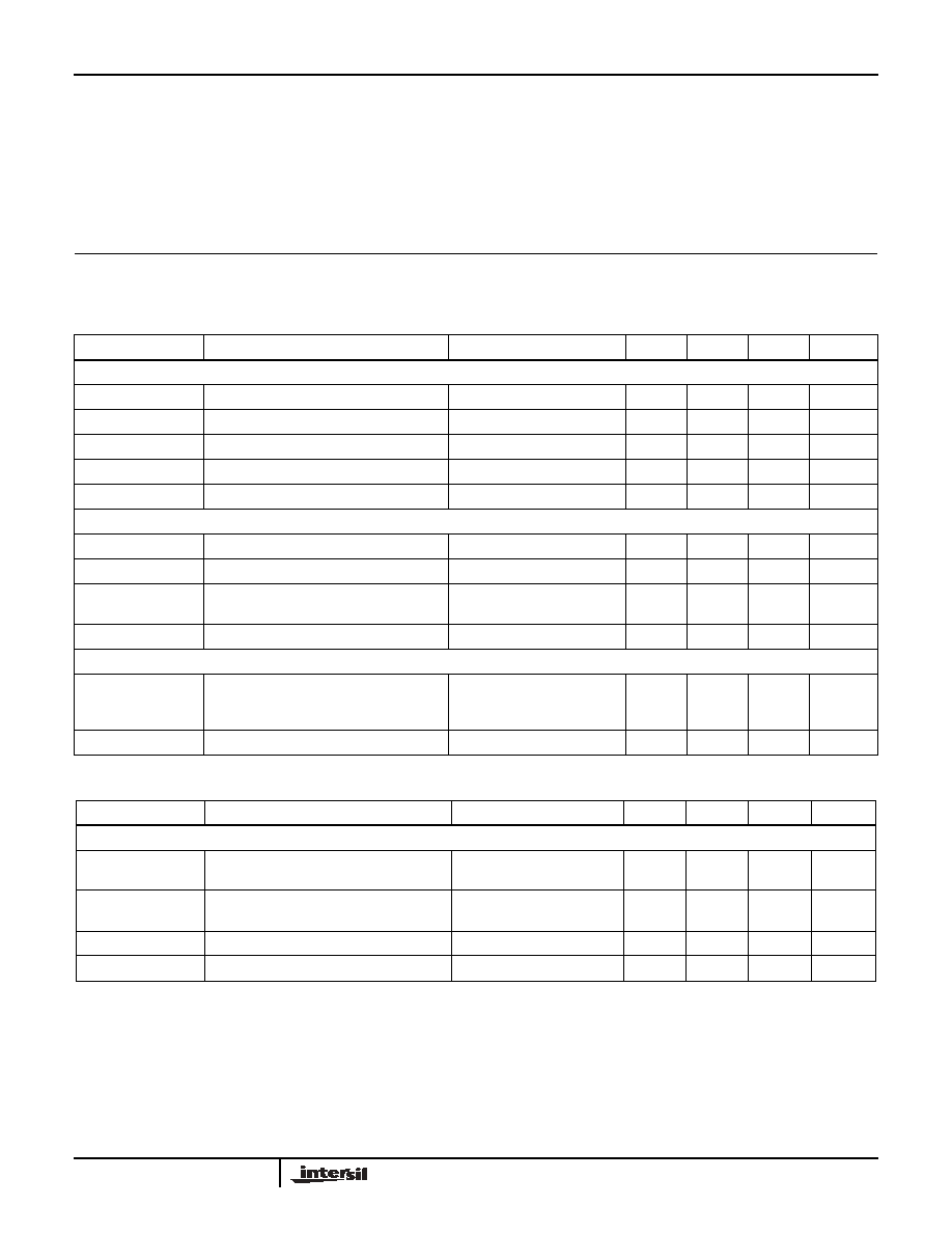
DC Electrical Specifications
T
A
= 25∞C, V = 15V unless otherwise specified
PARAMETER
DESCRIPTION
TEST CONDITIONS
MIN
TYP
MAX
UNITS
INPUT
V
IH
Logic "1" Input Voltage
2.4
V
I
IH
Logic "1" Input Current
@V+
0.1
10
µA
V
IL
Logic "0" Input Voltage
0.8
V
I
IL
Logic "0" Input Current
@0V
0.1
10
µA
V
HVS
Input Hysteresis
0.3
V
OUTPUT
R
OH
Pull-Up Resistance
I
OUT
= -100mA
3
6
R
OL
Pull-Down Resistance
I
OUT
= +100mA
4
6
I
PK
Peak Output Current
Source
Sink
2
2
A
I
DC
Continuous Output Current
Source/Sink
100
mA
POWER SUPPLY
I
S
Power Supply Current
Inputs High/EL7202
Inputs High/EL7212
Inputs High/EL7222
4.5
1
2.5
7.5
2.5
5.0
mA
V
S
Operating Voltage
4.5
15
V
AC Electrical Specifications
T
A
= 25∞C, V = 15V unless otherwise specified
PARAMETER
DESCRIPTION
TEST CONDITIONS
MIN
TYP
MAX
UNITS
SWITCHING CHARACTERISTICS
t
R
Rise Time
C
L
= 500pF
C
L
= 1000pF
7.5
10
20
ns
t
F
Fall Time
C
L
= 500pF
C
L
= 1000pF
10
13
20
ns
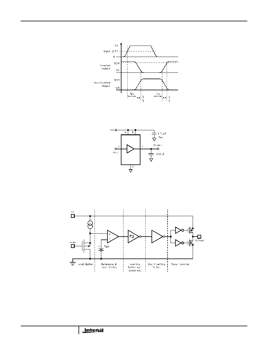
t
D1
Turn-On Delay Time
See Timing Table
18
25
ns
t
D2
Turn-Off Delay Time
See Timing Table
20
25
ns
EL7202, EL7212, EL7222

5
Typical Performance Curves
Max Power/Derating Curves
Switch Threshold vs Supply Voltage
Peak Drive vs Supply Voltage
Input Current vs Voltage
Quiescent Supply Current
"ON" Resistance vs Supply Voltage
EL7202, EL7212, EL7222