1
Æ
FN4805.10
ICL3221, ICL3222, ICL3223, ICL3232,
ICL3241, ICL3243
One Microamp Supply-Current, +3V to +5.5V,
250kbps, RS-232 Transmitters/Receivers
The Intersil ICL32XX devices are 3.0V to 5.5V powered
RS-232 transmitters/receivers which meet ElA/TIA-232 and
V.28/V.24 specifications, even at V
CC
= 3.0V. Targeted
applications are PDAs, Palmtops, and notebook and laptop
computers where the low operational, and even lower
standby, power consumption is critical. Efficient on-chip
charge pumps, coupled with manual and automatic
powerdown functions (except for the ICL3232), reduce the
standby supply current to a 1
µ
A trickle. Small footprint
packaging, and the use of small, low value capacitors
ensure board space savings as well. Data rates greater than
250kbps are guaranteed at worst case load conditions. This
family is fully compatible with 3.3V only systems, mixed 3.3V
and 5.0V systems, and 5.0V only systems.
The ICL324X are 3-driver, 5-receiver devices that provide a
complete serial port suitable for laptop or notebook
computers. Both devices also include noninverting always-
active receivers for "wake-up" capability.
The ICL3221, ICL3223 and ICL3243, feature an
automatic powerdown function which powers down the
on-chip power-supply and driver circuits. This occurs when
an attached peripheral device is shut off or the RS-232
cable is removed, conserving system power automatically
without changes to the hardware or operating system.
These devices power up again when a valid RS-232
voltage is applied to any receiver input.
Table 1 summarizes the features of the devices represented
by this data sheet, while Application Note AN9863
summarizes the features of each device comprising the
ICL32XX 3V family.
Features
∑
±
15kV ESD Protected (Human Body Model)
∑ Drop in Replacements for MAX3221, MAX3222,
MAX3223, MAX3232, MAX3241, MAX3243, SP3243
∑ ICL3221 is Low Power, Pin Compatible Upgrade for 5V
MAX221
∑ ICL3222 is Low Power, Pin Compatible Upgrade for 5V
MAX242, and SP312A
∑ ICL3232 is Low Power Upgrade for HIN232/ICL232 and
Pin Compatible Competitor Devices
∑ Meets EIA/TIA-232 and V.28/V.24 Specifications at 3V
∑ Latch-Up Free
∑ On-Chip Voltage Converters Require Only Four External
0.1
µ
F Capacitors
∑ Manual and Automatic Powerdown Features (Except
ICL3232)
∑ Guaranteed Mouse Driveability (ICL324X Only)
∑ Receiver Hysteresis For Improved Noise Immunity
∑ Guaranteed Minimum Data Rate . . . . . . . . . . . . . 250kbps
∑ Guaranteed Minimum Slew Rate . . . . . . . . . . . . . . . 6V/
µ
s
∑ Wide Power Supply Range . . . . . . . Single +3V to +5.5V
∑ Low Supply Current in Powerdown State. . . . . . . . . . .1
µ
A
Applications
∑ Any System Requiring RS-232 Communication Ports
- Battery Powered, Hand-Held, and Portable Equipment
- Laptop Computers, Notebooks, Palmtops
- Modems, Printers and other Peripherals
- Digital Cameras
- Cellular/Mobile Phones
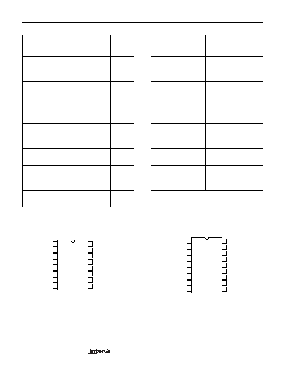
TABLE 1. SUMMARY OF FEATURES
PART
NUMBER
NO. OF
Tx.
NO. OF
Rx.
NO. OF
MONITOR Rx.
(R
OUTB
)
DATA
RATE
(kbps)
Rx. ENABLE
FUNCTION?
READY
OUTPUT?
MANUAL
POWER-
DOWN?
AUTOMATIC
POWERDOWN
FUNCTION?
ICL3221
1
1
0
250
YES
NO
YES
YES
ICL3222
2
2
0
250
YES
NO
YES
NO
ICL3223
2
2
0
250
YES
NO
YES
YES
ICL3232
2
2
0
250
NO
NO
NO
NO
ICL3241
3
5
2
250
YES
NO
YES
NO
ICL3243
3
5
1
250
NO
NO
YES
YES
Data Sheet
July 2002
CAUTION: These devices are sensitive to electrostatic discharge; follow proper IC Handling Procedures.
1-888-INTERSIL or 321-724-7143
|
Intersil (and design) is a trademark of Intersil Americas Inc.
Copyright © Intersil Americas Inc. 2002. All Rights Reserved
3
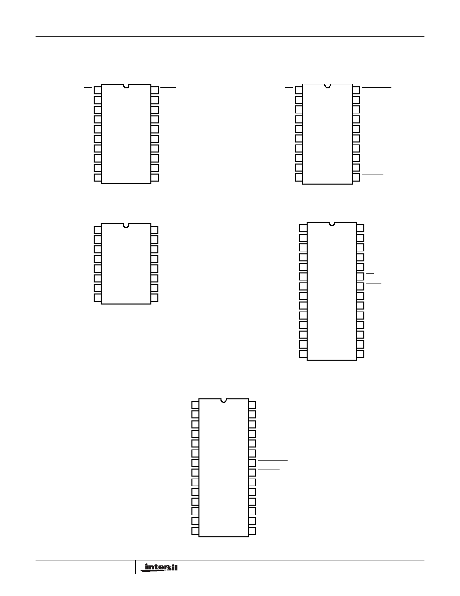
ICL3222 (SSOP, TSSOP)
TOP VIEW
ICL3223 (PDIP, SSOP, TSSOP)
TOP VIEW
ICL3232 (PDIP, SOIC, SSOP, TSSOP)
TOP VIEW
ICL3241 (SOIC, SSOP, TSSOP)
TOP VIEW
ICL3243 (SOIC, SSOP, TSSOP)
TOP VIEW
Pinouts
(Continued)
EN
C1+
V+
C1-
C2+
C2-
V-
T2
OUT
R2
IN
SHDN
GND
T1
OUT
R1
IN
R1
OUT
T1
IN
NC
V
CC
NC
T2
IN
20
19
18
17
16
15
14
13
12
11
1
2
3
4
5
6
7
8
9
10
R2
OUT
EN
C1+
V+
C1-
C2+
C2-
V-
T2
OUT
R2
IN
FORCEOFF
GND
T1
OUT
R1
IN
R1
OUT
T1
IN
INVALID
V
CC
FORCEON
T2
IN
20
19
18
17
16
15
14
13
12
11
1
2
3
4
5
6
7
8
9
10
R2
OUT
C1+
V+
C1-
C2+
C2-
V-
T2
OUT
R2
IN
V
CC
T1
OUT
R1
IN
R1
OUT
T1
IN
R2
OUT
GND
T2
IN
16
15
14
13
12
11
10
9
1
2
3
4
5
6
7
8
C2+
C2-
V-
R1
IN
R2
IN
R3
IN
R4
IN
R5
IN
T1
OUT
T3
OUT
T3
IN
T2
IN
T1
IN
C1+
V
CC
GND
C1-
EN
R1
OUTB
R1
OUT
R2
OUT
R3
OUT
R4
OUT
R5
OUT
V+
SHDN
R2
OUTB
28
27
26
25
24
23
22
21
20
19
18
17
16
15
1
2
3
4
5
6
7
8
9
10
11
12
13
14
T2
OUT
C2+
C2-
V-
R1
IN
R2
IN
R3
IN
R4
IN
R5
IN
T1
OUT
T3
OUT
T3
IN
T2
IN
T1
IN
C1+
V
CC
GND
C1-
FORCEON
INVALID
R1
OUT
R2
OUT
R3
OUT
R4
OUT
R5
OUT
V+
FORCEOFF
R2
OUTB
28
27
26
25
24
23
22
21
20
19
18
17
16
15
1
2
3
4
5
6
7
8
9
10
11
12
13
14
T2
OUT
ICL3221, ICL3222, ICL3223, ICL3232, ICL3241, ICL3243

4
Pin Descriptions
PIN
FUNCTION
V
CC
System power supply input (3.0V to 5.5V).
V+
Internally generated positive transmitter supply (+5.5V).
V-
Internally generated negative transmitter supply (-5.5V).
GND
Ground connection.
C1+
External capacitor (voltage doubler) is connected to this lead.
C1-
External capacitor (voltage doubler) is connected to this lead.
C2+
External capacitor (voltage inverter) is connected to this lead.
C2-
External capacitor (voltage inverter) is connected to this lead.
T
IN
TTL/CMOS compatible transmitter Inputs.
T
OUT
RS-232 level (nominally
±
5.5V) transmitter outputs.
R
IN
RS-232 compatible receiver inputs.
R
OUT
TTL/CMOS level receiver outputs.
R
OUTB
TTL/CMOS level, noninverting, always enabled receiver outputs.
INVALID
Active low output that indicates if no valid RS-232 levels are present on any receiver input.
EN
Active low receiver enable control; doesn't disable R
OUTB
outputs.
SHDN
Active low input to shut down transmitters and on-board power supply, to place device in low power mode.
FORCEOFF Active low to shut down transmitters and on-chip power supply. This overrides any automatic circuitry and FORCEON (see Table 2).
FORCEON Active high input to override automatic powerdown circuitry thereby keeping transmitters active. (FORCEOFF must be high).
ICL3221, ICL3222, ICL3223, ICL3232, ICL3241, ICL3243
5
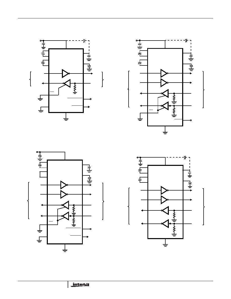
Typical Operating Circuits
ICL3221
ICL3222
ICL3223
ICL3232
15
V
CC
T1
OUT
T1
IN
T
1
0.1
µ
F
+0.1
µ
F
+
0.1
µ
F
11
13
2
4
3
7
V+
V-
C1+
C1-
C2+
C2-
+
0.1
µ
F
5
6
R1
OUT
R1
IN
R
1
8
9
5k
C
1
C
2
+ C
3
C
4
EN
1
GND
+3.3V
+
0.1
µ
F
14
TTL
/
C
M
O
S
L
O
G
I
C
LE
V
E
LS
RS
-
2
3
2
LE
V
E
LS
FORCEON
FORCEOFF
12
16
V
CC
10
INVALID
TO POWER
CONTROL
LOGIC
+
C
3
(OPTIONAL CONNECTION, NOTE)
NOTE: THE NEGATIVE TERMINAL OF C
3
CAN BE
CONNECTED TO EITHER V
CC
OR GND
17
V
CC
T1
OUT
T2
OUT
T1
IN
T2
IN
T
1
T
2
0.1
µ
F
+
0.1
µ
F
+
0.1
µ
F
12
11
15
8
2
4
3
7
V+
V-
C1+
C1-
C2+
C2-
+
0.1
µ
F
5
6
R1
OUT
R1
IN
14
5k
R2
OUT
R2
IN
9
10
5k
13
C
1
C
2
+ C
3
C
4
EN
SHDN
1
GND
18
+3.3V
+
0.1
µ
F
16
V
CC
T
TL/
C
M
O
S
LO
G
I
C
LE
V
E
LS
R
S
-
232
LE
V
E
LS
R
1
R
2
+
C
3
(OPTIONAL CONNECTION, NOTE)
NOTE: THE NEGATIVE TERMINAL OF C
3
CAN BE
CONNECTED TO EITHER V
CC
OR GND
19
V
CC
T1
OUT
T2
OUT
T1
IN
T2
IN
T
1
T
2
0.1
µ
F
+0.1
µ
F
+
0.1
µ
F
13
12
17
8
2
4
3
7
V+
V-
C1+
C1-
C2+
C2-
+
0.1
µ
F
5
6
R1
OUT
R1
IN
16
5k
R2
OUT
R2
IN
9
10
5k
15
C
1
C
2
+C
3
C
4
EN
1
GND
+3.3V
+ 0.1
µ
F
18
TTL
/
C
M
O
S
L
O
G
I
C
LE
V
E
LS
RS
-
2
3
2
L
EVE
L
S
R
1
R
2
FORCEON
FORCEOFF
14
20
V
CC
11
INVALID
TO POWER
CONTROL LOGIC
16
V
CC
T1
OUT
T2
OUT
T1
IN
T2
IN
T
1
T
2
0.1
µ
F
+
0.1
µ
F
+
0.1
µ
F
11
10
14
7
1
3
2
6
V+
V-
C1+
C1-
C2+
C2-
+
0.1
µ
F
4
5
R1
OUT
R1
IN
13
5k
R2
OUT
R2
IN
8
9
5k
12
C
1
C
2
+ C
3
C
4
GND
+3.3V
+
0.1
µ
F
15
T
TL/
C
M
O
S
LO
G
I
C
LE
V
E
L
S
RS
-
2
3
2
LE
V
E
LS
R
1
R
2
+
C
3
(OPTIONAL CONNECTION, NOTE)
NOTE: THE NEGATIVE TERMINAL OF C
3
CAN BE
CONNECTED TO EITHER V
CC
OR GND
ICL3221, ICL3222, ICL3223, ICL3232, ICL3241, ICL3243