1
Æ
FN8038.3
ISL4238E, ISL4244E, ISL4245E
QFN Packaged,
±
15kV ESD Protected,
+2.7V to +5.5V, 10Nanoamp, 250kbps/
1Mbps, RS-232 Transceivers with
Enhanced Automatic Powerdown
The Intersil ISL4238E/44E/45E devices are 2.7V to 5.5V
powered RS-232 transmitters/receivers which meet
ElA/TIA-232 and V.28/V.24 specifications, even at
V
CC
= 3.0V. Additionally, they provide
±
15kV ESD protection
(IEC6100-4-2 Air Gap and Human Body Model) on
transmitter outputs and receiver inputs (RS-232 pins).
Targeted applications are PDAs, Palmtops, and notebook
and laptop computers where the low operational, and even
lower standby, power consumption is critical. Efficient on-
chip charge pumps, coupled with manual and enhanced
automatic powerdown functions, reduce the standby supply
current to a
10nA
trickle. Tiny 5mm x 5mm Quad Flat No-
Lead (QFN) packaging and the use of small, low value
capacitors ensure board space savings as well. Data rates
greater than 250kbps (ISL4238E/44E)/1Mbps (ISL4245E)
are guaranteed at worst case load conditions.
The ISL424XE are 3 driver, 5 receiver (DTE) devices that,
coupled with the QFN package, provide the industry's
smallest, lowest power complete serial port suitable for
PDAs, and laptop or notebook computers. The 5x5 QFN
requires 60% less board area than a 28 lead TSSOP, and is
nearly 20% thinner. The devices also include a noninverting
always-active receiver for "wake-up" capability.
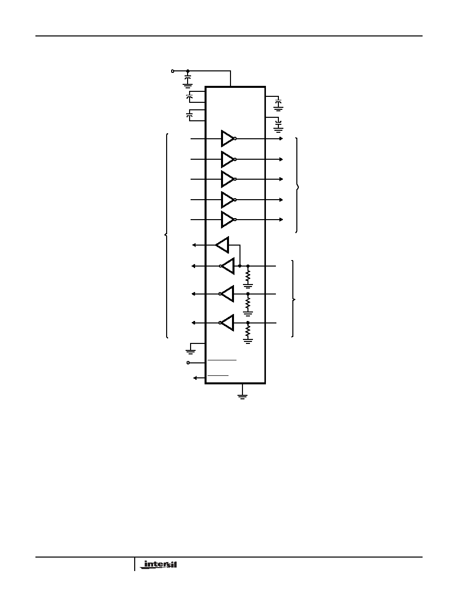
The ISL4238E is a 5 driver, 3 receiver device optimized for
DCE applications with full hardware handshaking. It also
includes a noninverting always-active receiver for RING
INDICATOR monitoring. Transmitter and logic inputs include
active feedback resistors that retain the input state once
driven to a valid logic level.
These devices feature an enhanced automatic
powerdown function which powers down the on-chip power-
supply and driver circuits. This occurs when all receiver and
transmitter inputs detect no signal transitions for a period of
30sec. These devices power back up, automatically,
whenever they sense a transition on any transmitter or
receiver input.
Table 1 summarizes the features of the ISL4238E/4XE, while
Application Note AN9863 summarizes the features of each
device comprising the 3V RS-232 family.
Features
∑ Parameters Fully Specified for 10% Tolerance Supplies
and Full Industrial Temp Range
∑ Available in Small QFN (5mm x 5mm) Package which is
60% Smaller than a 28 Lead TSSOP
∑ ESD Protection for RS-232 I/O Pins to
±
15kV (IEC6100)
∑ DTE (ISL4244E/45E) and DCE (ISL4238E) Versions
∑ Lowest Supply Current in Powerdown . . . . . . . . . . . .10nA
∑ Active Feedback Resistors on T
X
and Logic Inputs
(ISL4238E)
∑ Flow Through Pinouts
∑ Manual and Enhanced Automatic Powerdown Features
∑ Guaranteed Minimum Data Rate
250kbps (ISL4238E/44E) / 1Mbps (ISL4245E)
∑ Latch-Up Free
∑ On-Chip Charge Pumps Require Only Four External
0.1
µ
F Capacitors
∑ Wide Power Supply Range. . . . . . . Single +2.7V to +5.5V
∑ Meets EIA/TIA-232 and V.28/V.24 Specifications at 3V
∑ RS-232 Compatible with V
CC
= 2.7V
∑
Pb-free Available as an Option
Applications
∑ Any Space Constrained System Requiring RS-232 Ports
- Battery Powered, Hand-Held, and Portable Equipment
- Laptop Computers, Notebooks
- PDAs and Palmtops, Data Cables
- Cellular/Mobile Phones, Digital Cameras, GPS
Receivers
Related Literature
∑ Technical Brief TB363 "Guidelines for Handling and
Processing Moisture Sensitive Surface Mount Devices"
∑ Technical Brief TB379 "Thermal Characterization of
Packages for ICs"
∑ Technical Brief TB389 "PCB Land Pattern Design and
Surface Mount Guidelines for QFN Packages"
Data Sheet
April 2004
CAUTION: These devices are sensitive to electrostatic discharge; follow proper IC Handling Procedures.
1-888-INTERSIL or 321-724-7143
|
Intersil (and design) is a registered trademark of Intersil Americas Inc.
Copyright © Intersil Americas Inc. 2004. All Rights Reserved
All other trademarks mentioned are the property of their respective owners.

2
TABLE 1. SUMMARY OF FEATURES
PART
NUMBER
NO. OF
Tx.
NO. OF
Rx.
CONFIG.
QFN PKG.
NO. OF
MONITOR Rx.
(R
OUTB
)
DATA
RATE
(kbps)
Rx. ENABLE
FUNCTION?
MANUAL
POWER-
DOWN?
ENHANCED
AUTOMATIC
POWERDOWN
FUNCTION?
ISL4238E
5
3
DCE
5x5
1
250
NO
YES
YES
ISL4244E
3
5
DTE
5x5
1
250
NO
YES
YES
ISL4245E
3
5
DTE
5x5
1
1000
NO
YES
YES
Ordering Information
PART NO.
(BRAND)
TEMP.
RANGE (∞C)
PACKAGE
PKG.
DWG. #
ISL4238EIR
(4238EIR)
-40 to 85
32 Ld QFN
L32.5x5
ISL4238EIRZ
(4238EIR) (Note)
-40 to 85
32 Ld QFN (Pb-free)
L32.5x5
ISL4238EIR-T
(4238EIR)
-40 to 85
Tape & Reel
L32.5x5
ISL4238EIRZ-T
(4238EIR) (Note)
-40 to 85
Tape & Reel (Pb-free) L32.5x5
ISL4244EIR
(4244EIR)
-40 to 85
32 Ld QFN
L32.5x5
ISL4244EIRZ
(4244EIR) (Note)
-40 to 85
32 Ld QFN (Pb-free)
L32.5x5
ISL4244EIR-T
(4244EIR)
-40 to 85
Tape & Reel
L32.5x5
ISL4244EIRZ-T
(4244EIR) (Note)
-40 to 85
Tape & Reel (Pb-free) L32.5x5
ISL4245EIR
(4245EIR)
-40 to 85
32 Ld QFN
L32.5x5
ISL4245EIRZ
(4245EIR) (Note)
-40 to 85
32 Ld QFN (Pb-free)
L32.5x5
ISL4245EIR-T
(4245EIR)
-40 to 85
Tape & Reel
L32.5x5
ISL4245EIRZ-T
(4245EIR) (Note)
-40 to 85
Tape & Reel (Pb-free) L32.5x5
NOTE: Intersil Pb-free products employ special Pb-free material
sets; molding compounds/die attach materials and 100% matte tin
plate termination finish, which is compatible with both SnPb and
Pb-free soldering operations. Intersil Pb-free products are MSL
classified at Pb-free peak reflow temperatures that meet or exceed
the Pb-free requirements of IPC/JEDEC J Std-020B.
Ordering Information
(Continued)
PART NO.
(BRAND)
TEMP.
RANGE (∞C)
PACKAGE
PKG.
DWG. #
Pinouts
ISL4238E (QFN)
TOP VIEW
ISL4244E, ISL4245E (QFN)
TOP VIEW
T1
OUT
T2
OUT
T3
OUT
R1
IN
R2
IN
T4
OUT
R3
IN
T1
IN
T2
IN
T3
IN
R1
OUT
R2
OUT
T4
IN
R3
OUT
T5
OUT
FORCEON
FORCE
OFF
INV
A
LI
D
NC
T5
IN
R1
OU
T
B
C2-
GND
C2+
C1+
V+
C1-
V
CC
NC
V-
NC
1
2
3
4
5
6
7
8
24
23
22
21
20
19
18
17
32
31
30
29
28
27
26
25
9
10
11
12
13
14
15
16
NC
R1
IN
R2
IN
R3
IN
R4
IN
R5
IN
T1
OUT
T2
OUT
C1-
FORCEON
FORCEOFF
INVALID
R2
OUTB
R1
OUT
R2
OUT
T3
OUT
T3
IN
T2
IN
T1
IN
R5
OU
T
R3
OU
T
R4
OU
T
V-
C2-
C2+
C1+
V+
GND
V
CC
NC
NC
NC
NC
1
2
3
4
5
6
7
8
24
23
22
21
20
19
18
17
32
31
30
29
28
27
26
25
9
10
11
12
13
14
15
16
ISL4238E, ISL4244E, ISL4245E

3
Pin Descriptions
PIN
FUNCTION
V
CC
System power supply input (2.7V to 5.5V).
V+
Internally generated positive transmitter supply (+5.5V).
V-
Internally generated negative transmitter supply (-5.5V).
GND
Ground connection.
C1+
External capacitor (voltage doubler) is connected to this lead.
C1-
External capacitor (voltage doubler) is connected to this lead.
C2+
External capacitor (voltage inverter) is connected to this lead.
C2-
External capacitor (voltage inverter) is connected to this lead.
T
IN
TTL/CMOS compatible transmitter Inputs. (Note 1)
T
OUT
±
15kV ESD Protected
,
RS-232 level (nominally
±
5.5V) transmitter outputs.
R
IN
±
15kV ESD Protected
,
RS-232 compatible receiver inputs.
R
OUT
TTL/CMOS level receiver outputs.
R
OUTB
TTL/CMOS level, noninverting, always enabled receiver outputs.
INVALID
Active low output that indicates if no valid RS-232 levels are present on any receiver input.
FORCEOFF Active low to shut down transmitters and on-chip power supply. This overrides any automatic circuitry and FORCEON (see Table 2).
FORCEON
Active high input to override automatic powerdown circuitry thereby keeping transmitters active. (FORCEOFF must be high).
NOTE:
1. ISL4238E input pins incorporate positive feedback resistors. Once the input is driven to a valid logic level, the feedback resistor maintains that
logic level until V
CC
is removed. Unused transmitter inputs may be left unconnected by the user.
ISL4238E, ISL4244E, ISL4245E