1
Æ
FN9111.3
CAUTION: These devices are sensitive to electrostatic discharge; follow proper IC Handling Procedures.
1-888-INTERSIL or 321-724-7143
|
Intersil (and design) is a registered trademark of Intersil Americas Inc.
Copyright © Intersil Americas Inc. 2003-2004. All Rights Reserved.
All other trademarks mentioned are the property of their respective owners.
ISL6740, ISL6741
Flexible Double Ended Voltage and
Current Mode PWM Controllers
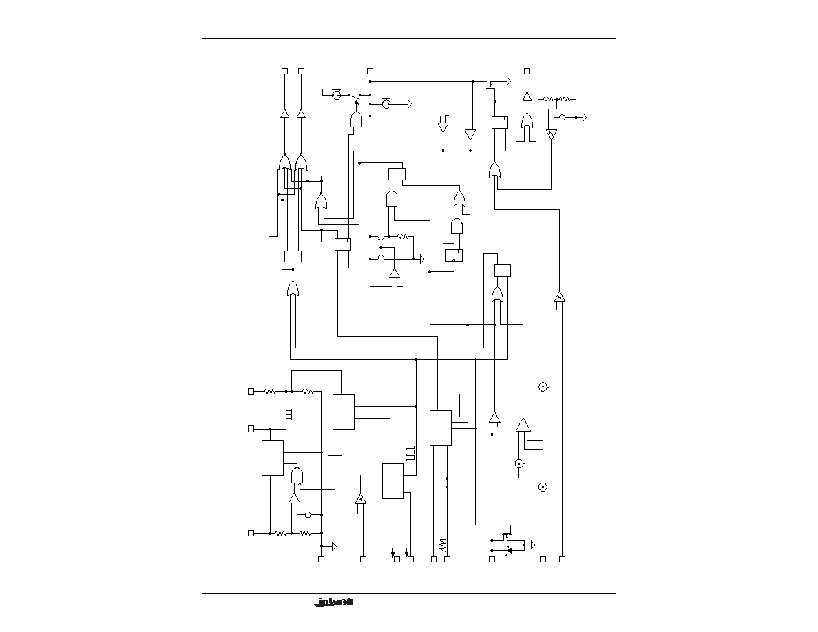
The ISL6740, ISL6741 family of adjustable frequency, low
power, pulse width modulating (PWM) voltage mode
(ISL6740) and current mode (ISL6741) controllers is
designed for a wide range of power conversion applications
using half-bridge, full bridge, and push-pull configurations.
These controllers provide an extremely flexible oscillator that
allows precise control of frequency, duty cycle, and
deadtime.
This advanced BiCMOS design features low operating
current, adjustable switching frequency up to 1MHz,
adjustable soft start, internal and external over temperature
protection, fault annunciation, and a bidirectional SYNC
signal that allows the oscillator to be locked to paralleled
units or to an external clock for noise sensitive applications.
Features
∑ Precision Duty Cycle and Deadtime Control
∑ 95
µ
A Startup Current
∑ Adjustable Delayed Over Current Shutdown and Re-Start
(ISL6740)
∑ Adjustable Short Circuit Shutdown and Re-Start
∑ Adjustable Oscillator Frequency Up to 2MHz
∑ Bidirectional Synchronization
∑ Inhibit Signal
∑ Internal Over Temperature Protection
∑ System Over Temperature Protection Using a Thermistor
or Sensor
∑ Adjustable Soft Start
∑ Adjustable input Under Voltage Lockout
∑ Fault Signal
∑ Tight Tolerance Voltage Reference Over Line, Load, and
Temperature
∑ Pb-free available
Applications
∑ Telecom and Datacom Power
∑ Wireless Base Station Power
∑ File Server Power
∑ Industrial Power Systems
∑ DC Transformers and Buss Regulators
Pinout
ISL6740, ISL6741 (SOIC, TSSOP)
TOP VIEW
Ordering Information
PART NUMBER
TEMP. RANGE
(
o
C)
PACKAGE
PKG.
DWG. #
ISL6740IB
-40 to 105
16 Ld SOIC
M16.15
ISL6740IBZ
(See Note)
-40 to 105
16 Ld SOIC
(Pb-free)
M16.15
ISL6740IV
-40 to 105
16 Ld TSSOP
M16.173
ISL6740IVZ
(See Note)
-40 to 105
16 Ld TSSOP
(Pb-free)
M16.173
ISL6741IB
-40 to 105
16 Ld SOIC
M16.15
ISL6741IBZ
(See Note)
-40 to 105
16 Ld SOIC
(Pb-free)
M16.15
ISL6741IV
-40 to 105
16 Ld TSSOP
M16.173
ISL6741IVZ
(See Note)
-40 to 105
16 Ld TSSOP
(Pb-free)
M16.173
Add -T suffix to part number for tape and reel packaging
NOTE: Intersil Pb-free products employ special Pb-free material
sets; molding compounds/die attach materials and 100% matte tin
plate termination finish, which is compatible with both SnPb and
Pb-free soldering operations. Intersil Pb-free products are MSL
classified at Pb-free peak reflow temperatures that meet or exceed
the Pb-free requirements of IPC/JEDEC J Std-020B.
x =
CONTROL MODE
0
Voltage Mode
1
Current Mode
OUTA
GND
SCSET
C
T
SYNC
CS
V
ERROR
OUTB
V
REF
V
DD
R
TD
R
TC
OTS
FAULT
1
2
3
4
5
6
7
16
15
14
13
12
11
10
8
9
UV
SS
Data Sheet
July 2004


