 | –≠–ª–µ–∫—Ç—Ä–æ–Ω–Ω—ã–π –∫–æ–º–ø–æ–Ω–µ–Ω—Ç: 25RIA80 | –°–∫–∞—á–∞—Ç—å:  PDF PDF  ZIP ZIP |
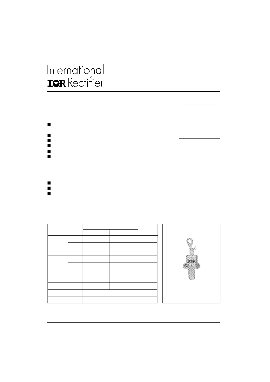
MEDIUM POWER THYRISTORS
Stud Version
25RIA SERIES
1
25A
Bulletin I2402 rev. A 07/00
25RIA
10 to 120
140 to 160
I
T(AV)
25
25
A
@ T
C
85
85
∞C
I
T(RMS)
40
40
A
I
TSM
@
50Hz
420
398
A
@ 60Hz
440
415
A
I
2
t
@
50Hz
867
795
A
2
s
@ 60Hz
790
725
A
2
s
V
DRM
/V
RRM
100 to 1200
1400 to 1600
V
t
q
typical
110
µs
T
J
- 65 to 125
∞C
Parameters
Units
Typical Applications
Medium power switching
Phase control applications
Can be supplied to meet stringent military,
aerospace and other high-reliability requirements
Major Ratings and Characteristics
Case Style
TO-208AA (TO-48)
Features
Improved glass passivation for high reliability
and exceptional stability at high temperature
High di/dt and dv/dt capabilities
Standard package
Low thermal resistance
Metric threads version available
Types up to 1600V V
DRM
/ V
RRM
www.irf.com
25RIA Series
2
www.irf.com
Bulletin I2402 rev. A 07/00
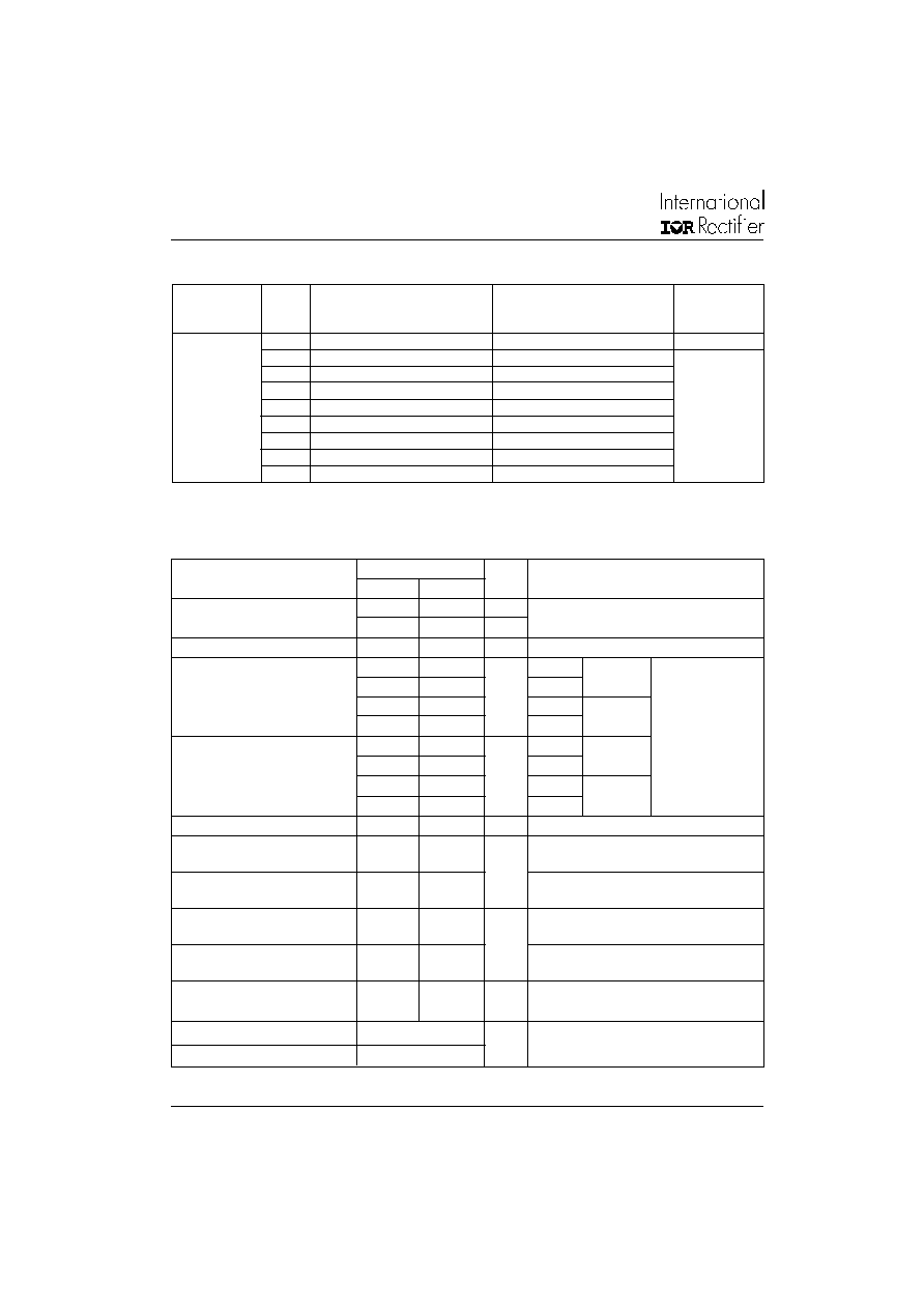
Voltage
V
DRM
/V
RRM
, max. repetitive
V
RSM
, maximum non-
I
DRM
/I
RRM
max.
Type number
Code
peak and off-state voltage (1)
repetitive peak voltage (2)
@ T
J
= T
J
max.
V
V
mA
10
100
150
20
20
200
300
40
400
500
60
600
700
25RIA
80
800
900
10
100
1000
1100
120
1200
1300
140
1400
1500
160
1600
1700
I
T(AV)
Max. average on-state current
25
25
A
180∞ sinusoidal conduction
@ Case temperature
85
85
∞C
I
T(RMS)
Max. RMS on-state current
40
40
A
I
TSM
Max. peak, one-cycle
420
398
A
t = 10ms
No voltage
non-repetitive surge current
440
415
t = 8.3ms
reapplied
350
335
t = 10ms
100% V
RRM
370
350
t = 8.3ms
reapplied
Sinusoidal half wave,
I
2
t
Maximum I
2
t for fusing
867
795
A
2
s
t = 10ms
No voltage
Initial T
J
= T
J
max.
790
725
t = 8.3ms
reapplied
615
560
t = 10ms
100% V
RRM
560
510
t = 8.3ms
reapplied
I
2
t
Maximum I
2
t for fusing
8670
7950
A
2
s
t = 0.1 to 10ms, no voltage reapplied, T
J
= T
J
max.
V
T(TO)1
Low level value of threshold
0.99
0.99
V
(16.7% x
x I
T(AV)
< I <
x I
T(AV)
), T
J
= T
J
max.
voltage
V
T(TO)
2
High level value of threshold
1.40
1.15
(I >
x I
T(AV)
),T
J
= T
J
max.
voltage
r
t1
Low level value of on-state
10.1
11.73
m
(16.7% x
x I
T(AV)
< I <
x I
T(AV)
), T
J
= T
J
max.
slope resistance
r
t2
High level value of on-state
5.7
10.05
(I >
x I
T(AV)
),T
J
= T
J
max.
slope resistance
V
TM
Max. on-state voltage
1.70
---
V
I
pk
= 79 A, T
J
= 25∞C
---
1.80
I
H
Maximum holding current
130
mA
T
J
= 25∞C. Anode supply 6V, resistive load,
I
L
Latching current
200
25RIA
10 to 120
140 to 160
Parameter
Units
Conditions
ELECTRICAL SPECIFICATIONS
Voltage Ratings
On-state Conduction
(1)
Units may be broken over non-repetitively in the off-state direction without damage, if dI/dt does not exceed 20A/µs
(2)
For voltage pulses with t
p
5ms
25RIA Series
3
www.irf.com
Bulletin I2402 rev. A 07/00
dv/dt
Max. critical rate of rise of
100
T
J
= T
J
max. linear to 100% rated V
DRM
off-state voltage
300 (*)
T
J
= T
J
max. linear to 67% rated V
DRM
V/µs
Parameter
25RIA
Units Conditions
Blocking
P
GM
Maximum peak gate power
8.0
T
J
= T
J
max.
P
G(AV)
Maximum average gate power
2.0
I
GM
Max. peak positive gate current
1.5
A
T
J
= T
J
max.
-V
GM
Maximum peak negative
10
V
T
J
= T
J
max.
gate voltage
I
GT
DC gate current required
90
T
J
= - 65∞C
to trigger
60
mA
T
J
= 25∞C
35
T
J
= 125∞C
V
GT
DC gate voltage required
3.0
T
J
= - 65∞C
to trigger
2.0
V
T
J
= 25∞C
1.0
V
T
J
= 125∞C
I
GD
DC gate current not to trigger
2.0
mA
T
J
= T
J
max., V
DRM
= rated value
V
GD
DC gate voltage not to trigger
0.2
V
T
J
= T
J
max.
V
DRM
= rated value
W
Max. required gate trigger current/
voltage are the lowest value which
will trigger all units 6V anode-to-
cathode applied
Max. gate current/ voltage not to
trigger is the max. value which
will not trigger any unit with rated
V
DRM
anode-to-cathode applied
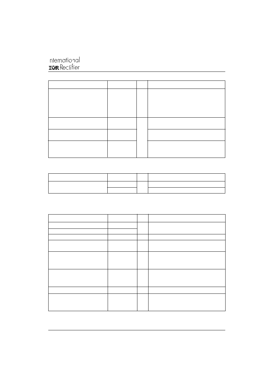
Parameter
25RIA
Units Conditions
Triggering
di/dt
Max. rate of rise of turned-on
T
J
= T
J
max., V
DM
= rated V
DRM
current
V
DRM
600V
200
A/µs
Gate pulse = 20V, 15
, t
p
= 6µs, t
r
= 0.1µs max.
V
DRM
800V
180
I
TM
= (2x rated di/dt) A
V
DRM
1000V
160
V
DRM
1600V
150
t
gt
Typical turn-on time
0.9
T
J
= 25∞C,
at = rated V
DRM
/V
RRM
, T
J
= 125∞C
t
rr
Typical reverse recovery time
4
µs
T
J
= T
J
max.,
I
TM
= I
T(AV)
, t
p
> 200µs, di/dt = -10A/µs
t
q
Typical turn-off time
110
T
J
= T
J
max., I
TM
= I
T(AV)
, t
p
> 200µs,
V
R
= 100V,
di/dt = -10A/µs, dv/dt = 20V/µs linear to
67% V
DRM
, gate bias 0V-100W
Parameter
25RIA
Units Conditions
Switching
(**) Available with: dv/dt = 1000V/µs, to complete code add S90 i.e. 25RIA160S90.
(*) t
q
= 10µsup to 600V, t
q
= 30µs up to 1600V available on special request.
25RIA Series
4
www.irf.com
Bulletin I2402 rev. A 07/00
R
thJC
Conduction
(The following table shows the increment of thermal resistence R
thJC
when devices operate at different conduction angles than DC)
180∞
0.17
0.13
K/W
T
J
= T
J
max.
120∞
0.21
0.22
90∞
0.27
0.30
60∞
0.40
0.42
30∞
0.69
0.70
Conduction angle
Sinusoidal conduction Rectangular conduction Units
Conditions
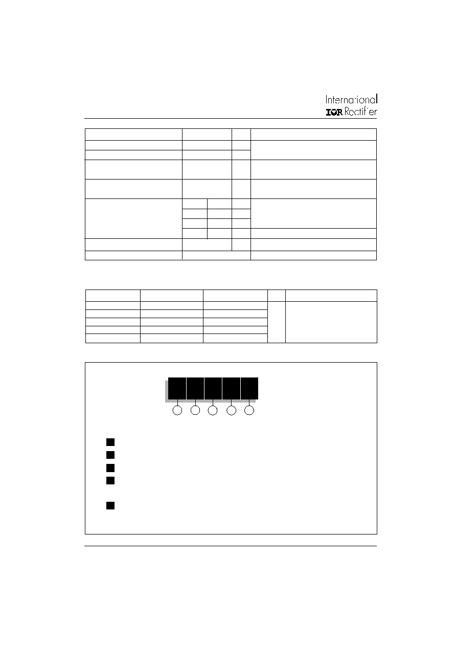
Ordering Information Table
1
25
RIA 160
M
S90
Device Code
4
3
2
1
-
Current code
2
-
Essential part number
3
-
Voltage code: Code x 10 = V
RRM
(See Voltage Rating Table)
4
-
None = Stud base TO-208AA (TO-48) 1/4" 28UNF-2A
M
= Stud base TO-208AA (TO-48) M6 X 1
5
-
Critical dv/dt: None = 300V/µs (Standard value)
S90 = 1000V/µs (Special selection)
5
T
J
Max. operating temperature range
- 65 to 125
∞ C
T
stg
Max. storage temperature range
- 65 to 125
∞ C
R
thJC
Max. thermal resistance,
0.75
K/W
DC operation
junction to case
R
thCS
Max. thermal resistance,
0.35
K/W
Mounting surface, smooth, flat and greased
case to heatsink
T
Mounting torque
to nut
to device
20(27.5)
25
lbf-in
Lubricated threads
0.23(0.32)
0.29
kgf.m
(Non-lubricated threads)
2.3(3.1)
2.8
Nm
Case style
TO-208AA (TO-48)
See Outline Table
Parameter
25RIA
Units Conditions
Thermal and Mechanical Specification
wt
Approximate weight
14 (0.49)
g (oz)
25RIA Series
5
www.irf.com
Bulletin I2402 rev. A 07/00
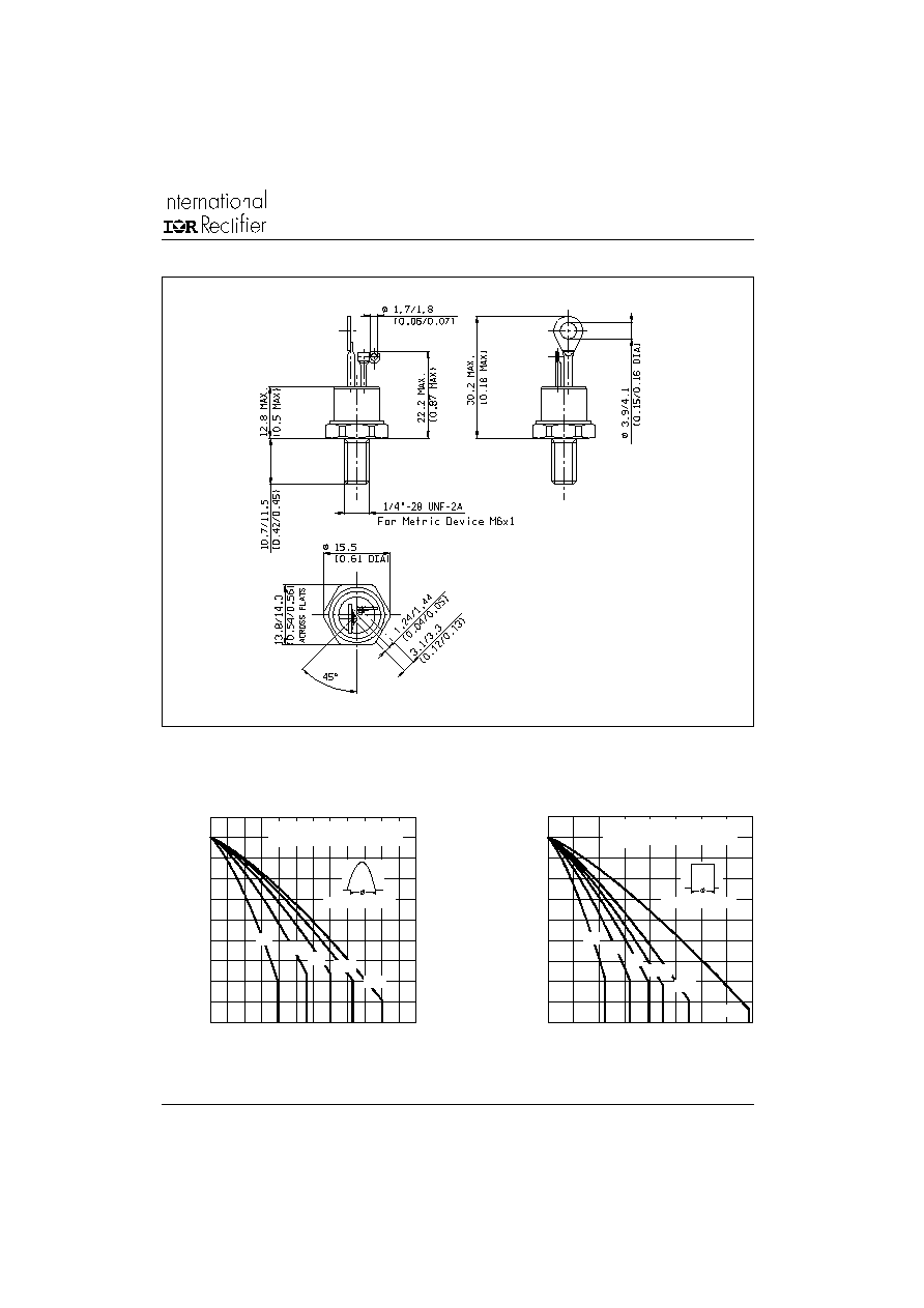
Outline Table
Fig. 1 - Current Ratings Characteristic
80
90
100
110
120
130
0
5
10
15
20
25
30
30∞
60∞
90∞
120∞
180∞
Average On-state Current (A)
M
a
xi
m
u
m
A
l
l
o
w
a
b
l
e C
a
se T
e
m
p
er
a
t
ur
e
(
∞
C
)
Conduction Angle
25RIA Series (100 to 1200V)
R (DC) = 0.75 K/W
thJC
80
90
100
110
120
130
0
10
20
30
40
DC
30∞
60∞
90∞
120∞
180∞
Average On-state Current (A)
Ma
x
i
m
u
m A
l
l
o
w
a
b
l
e
Ca
s
e
T
e
m
p
e
r
a
t
u
r
e
(
∞
C
)
Conduction Period
25RIA Series (100 to 1200V)
R (DC) = 0.75 K/W
thJC
Fig. 2 - Current Ratings Characteristic
Case Style TO-208AA (TO-48)
All dimensions in millimeters (inches)