 | –≠–ª–µ–∫—Ç—Ä–æ–Ω–Ω—ã–π –∫–æ–º–ø–æ–Ω–µ–Ω—Ç: 31DQ05 | –°–∫–∞—á–∞—Ç—å:  PDF PDF  ZIP ZIP |
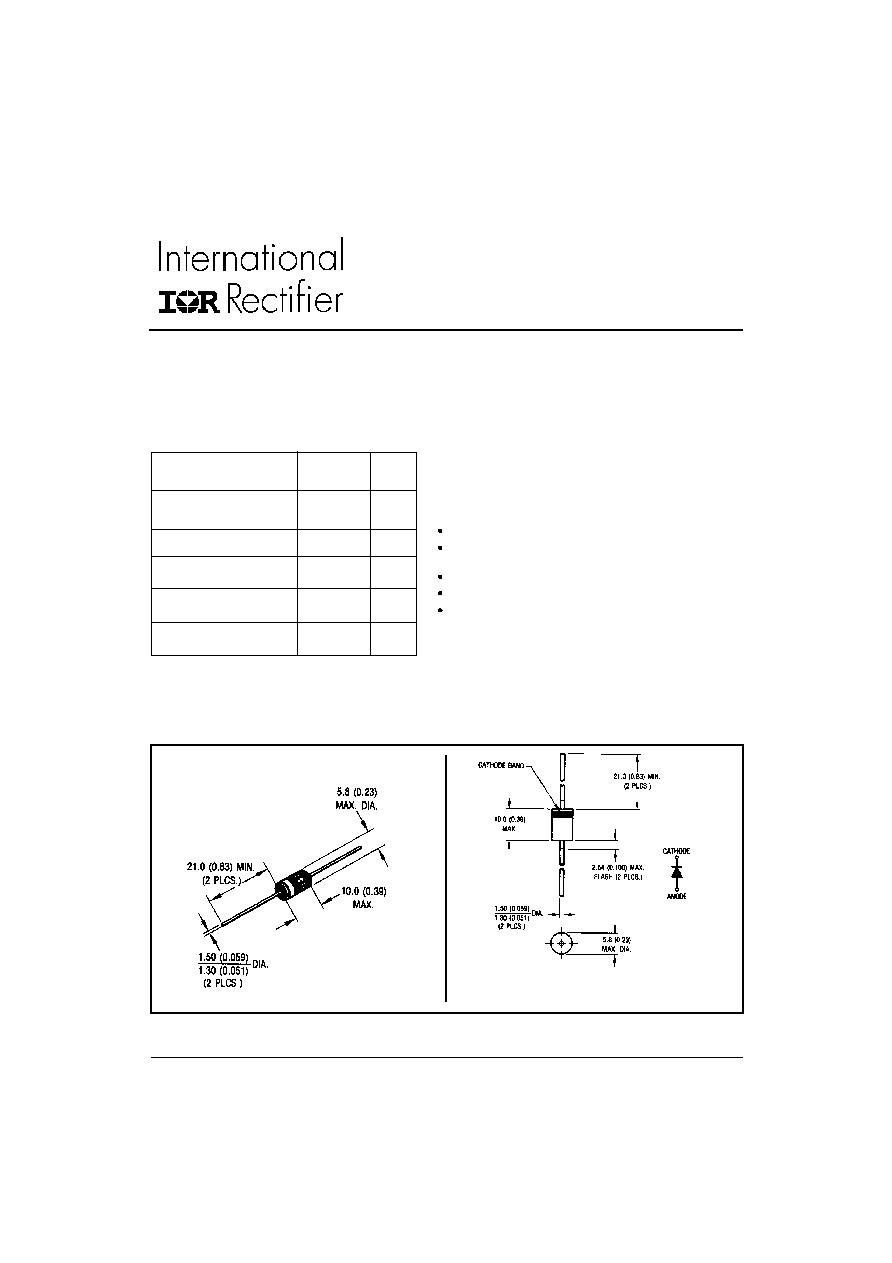
Dimensions in millimeters and inches
Outline C - 16
CASE STYLE AND DIMENSIONS
I
F(AV)
Rectangular
3.3
A
waveform
V
RRM
50/60
V
I
FSM
@ tp = 5 µs sine
340
A
V
F
@
3 Apk, T
J
= 25∞C
0.62
V
T
J
- 40 to 150
∞C
Characteristics
31DQ..
Units
The 31DQ.. axial leaded Schottky rectifier has been opti-
mized for very low forward voltage drop, with moderate
leakage. Typical applications are in switching power sup-
plies, converters, free-wheeling diodes, and reverse battery
protection.
Low profile, axial leaded outline
High purity, high temperature epoxy encapsulation for
enhanced mechanical strength and moisture resistance
Very low forward voltage drop
High frequency operation
Guard ring for enhanced ruggedness and long term
reliability
Description/Features
Major Ratings and Characteristics
SCHOTTKY RECTIFIER
3.3 Amp
31DQ05
31DQ06
PD-2.305 rev. B 02/2000
1
31DQ05, 31DQ06
PD-2.305 rev. B 02/2000
2
Part number
31DQ05
31DQ06
V
R
Max. DC Reverse Voltage (V)
V
RWM
Max. Working Peak Reverse Voltage (V)
Voltage Ratings
50
60
I
F(AV)
Max. Average Forward Current
3.3
A
50% duty cycle @ T
A
= 40 ∞C, rectangular wave form
* See Fig. 4
With cooling fins
I
FSM
Max. Peak One Cycle Non-Repetitive
340
5µs Sine or 3µs Rect. pulse
Surge Current * See Fig. 6
55
10ms Sine or 6ms Rect. pulse
Absolute Maximum Ratings
Parameters
31DQ..
Units
Conditions
A
Following any rated
load condition and with
rated V
RRM
applied
V
FM
Max. Forward Voltage Drop
0.62
V
@ 3A
* See Fig. 1
(1)
0.78
V
@ 6A
0.54
V
@ 3A
0.65
V
@ 6A
I
R M
Max. Reverse Leakage Current
2
mA
T
J
= 25 ∞C
* See Fig. 2
(1)
15
mA
T
J
= 125 ∞C
C
T
Typical Junction Capacitance
160
pF
V
R
= 5V
DC
, (test signal range 100Khz to 1Mhz) 25∞C
L
S
Typical Series Inductance
9.0
nH
Measured lead to lead 5mm from package body
T
J
= 25 ∞C
T
J
= 125 ∞C
V
R
= rated V
R
Parameters
31DQ.. Units
Conditions
Electrical Specifications
(1) Pulse Width < 300µs, Duty Cycle <2%
T
J
Max. Junction Temperature Range
-40 to 150
∞C
T
stg
Max. Storage Temperature Range
-40 to 150
∞C
R
thJA
Max. Thermal Resistance Junction
80
∞C/W DC operation
to Ambient
Without cooling fins
R
thJA
Typical Thermal Resistance Junction
34
∞C/W With fin 20 x 20 (0.79 x 0.79) 1.0 (0.04) thick.
to Ambient
Dimensions in millimeters (inches)
wt
Approximate Weight
1.2 (0.042) g (oz.)
Case Style
C - 16
Thermal-Mechanical Specifications
Parameters
31DQ..
Units
Conditions

31DQ05, 31DQ06
PD-2.305 rev. B 02/2000
3
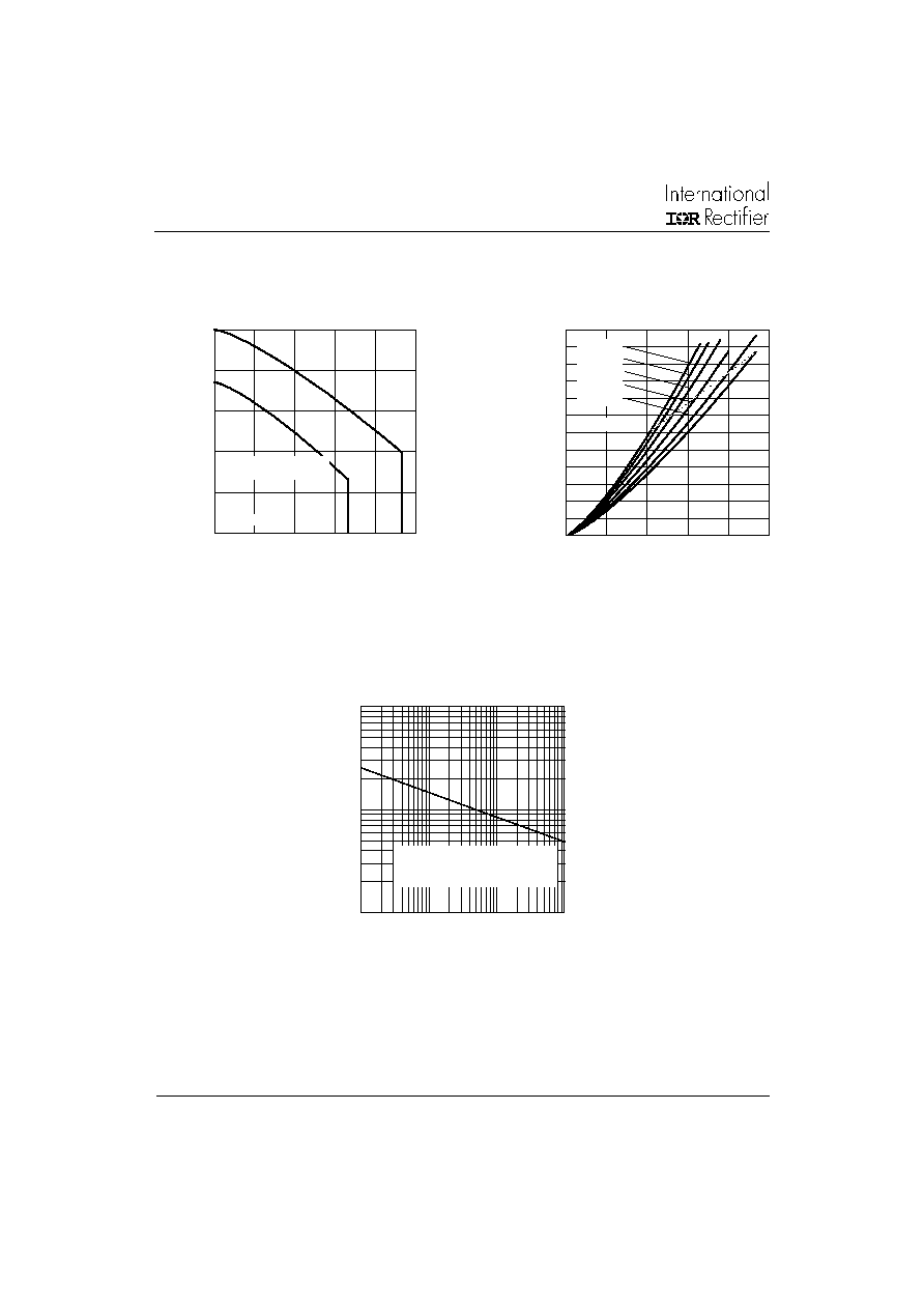
Fig. 1 - Max. Forward Voltage Drop Characteristics
Forward Voltage Drop - V
FM
(V)
Instantaneous Forward Current - I
F
(A)
Reverse Voltage - V
R
(V)
Reverse Voltage - V
R
(V)
Junction Capacitance - C
T
(pF)
Fig. 3 - Typical Junction Capacitance
Vs. Reverse Voltage
Fig. 2 - Typical Values Of Reverse Current
Vs. Reverse Voltage
Reverse Current - I
R
(mA)
0.1
1
10
0
0.2
0.4
0.6
0.8
1
T = 150∞C
T = 125∞C
T = 25∞C
J
J
J
0.001
0.01
0.1
1
10
100
0
20
40
60
125∞C
25∞C
T = 150∞C
J
10
100
1000
0
40
80
120
160
T = 25∞C
J
31DQ05, 31DQ06
PD-2.305 rev. B 02/2000
4
Average Forward Current - I
F
(AV)
(A)
Square Wave Pulse Duration - t
p
(microsec)
Fig. 6 - Max. Non-Repetitive Surge Current
Allowable Case Temperature - (
∞
C)
Non-Repetitive Surge Current - I
FSM
(A)
Fig. 5- Forward Power Loss Characteristics
Average Forward Current - I
F
(AV)
(A)
Average Power Loss - (Watts)
(2) Formula used: T
C
= T
J
- (Pd + Pd
REV
) x R
thJC
;
Pd = Forward Power Loss = I
F(AV)
x V
FM
@ (I
F(AV)
/
D) (see Fig. 6);
Pd
REV
= Inverse Power Loss = V
R1
x I
R
(1 - D); I
R
@ V
R1
= 80% rated V
R
Fig. 4 - Max. Allowable Case Temperature
Vs. Average Forward Current
0
0.5
1
1.5
2
2.5
3
0
1
2
3
4
5
DC
RMS Limit
D = 0.20
D = 0.25
D = 0.33
D = 0.50
D = 0.75
10
100
1000
10
100
1000
10000
At Any Rated Load Condition
And With Rated V Applied
Following Surge
RRM
0
30
60
90
120
150
0
1
2
3
4
5
DC
see note (2)
Square wave (D = 0.50)
80% Rated V applied
R

31DQ05, 31DQ06
PD-2.305 rev. B 02/2000
5
WORLD HEADQUARTERS:
233 Kansas St., El Segundo, California 90245 U.S.A Tel: (310) 322-3331 Fax: (310) 322-3332
EUROPEAN HEADQUARTERS:
Hurst Green, Oxted, Surrey RH8 9BB, U.K. Tel: ++ 44 1883 732020 Fax: ++ 44 1883 733408
IR CANADA:
7231 Victoria Park Ave., Suite #201, Markham, Ontario L3R 2Z8 Tel: (905) 475 1897. Fax: (905) 475 8801
IR GERMANY:
Saalburgstrasse 157, 61350 Bad Homburg Tel: ++ 49 6172 96590 Fax: ++ 49 6172 965933
IR ITALY:
Via Liguria 49, 10071 Borgaro, Torino Tel: ++ 39 11 4510111 Fax: ++ 39 11 4510220
IR FAR EAST:
K&H Bldg., 2F, 30-4 Nishi-Ikebukuro 3-Chome, Toshima-Ku, Tokyo, Japan 171 Tel: 81 3 3983 0086 Fax: 81 3 3983
0642
IR SOUTHEAST ASIA:
315 Outram Road, # 10-02 Tan Boon Liat Building, SINGAPORE 0316. Tel: 65 221 8371. Fax: 65 221 8372.
http://www.irf.com Fax-On-Demand: +44 1883 733420 Data and specifications subject to change without notice 11/97