ChipFind - документация

Электронный компонент: KIA79M12T

Скачать:  PDF   ZIP
2002. 8. 29
1/9
SEMICONDUCTOR
TECHNICAL DATA
KIA79M05T~KIA79M15T
BIPOLAR LINEAR INTEGRATED CIRCUIT
Revision No : 0
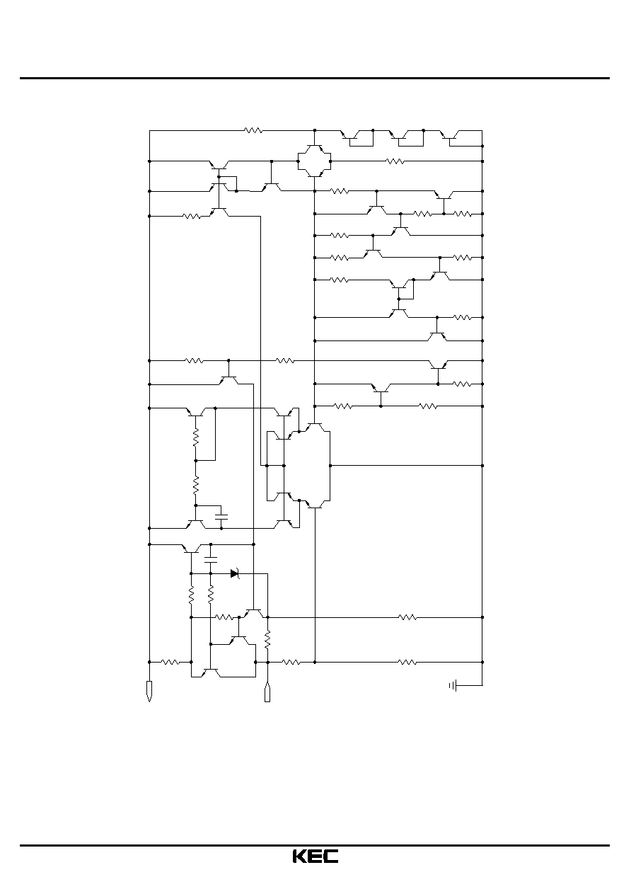
THREE TERMINAL NEGATIVE VOLTAGE REGULATORS
-5V, -8V, -12V, -15V.
KIA79M
Series of three-terminal regulators is available with
fixed output voltages of -5V, -8V, -12V, and -15V.
These devices need only one external component-a compensation
capacitor at the output. The KIA79MXX series is packaged in the
TO-126 power package, and is capable of supplying 0.5A of output
current. These regulators employ internal current limiting, safe area
protection, and thermal shutdown for protection against virtually
all overload conditions.
Low ground pin current of the KIA79MXX series allows output
voltage to be easily boosted above the preset value with a resistor
divider. The low quiescent current of these devices with a specified
maximum change with line and load ensures good regulation in the
voltage boosted mode.
FEATURES
Thermal, Short Circuit and Safe Area Protection.
High Ripple Rejection.
0.5A Output Current
4% Tolerance on Preset Output Voltage.
TO-126
H
J
MILLIMETERS
C
E
F
G
D
A
B
DIM
A
C
E
F
G
H
J
K
M
O
P
N
L
D
1. GND
2. INPUT
3. OUTPUT
K
L
M
N
O
P
8.3 MAX
5.8
0.7
3.1 0.1
3.5
11.0 0.3
2.9 MAX
1.0 MAX
1.9 MAX
0.75 0.15
14.0 MIN
2.3 0.1
0.75 0.15
1.6
3.4 MAX
B
1
2
3
+
_
+
_
+
_
+
_
+_
MAXIMUM RATINGS (Ta=25 )
CHARACTERISTIC
SYMBOL
RATING
UNIT
Input Voltage
V
IN
-35
V
Power Dissipation
T
C
=25
P
D
15
W
Without
Heatsink
1.5
Operating Junction Temperature
T
j
-40 150
Storage Temperature
T
stg
-55 150
Soldering Temperature (10 seconds)
T
sol
260
2002. 8. 29
2/9
KIA79M05T~KIA79M15T
Revision No : 0
EQUIVALENT CIRCUIT
R
0
Q
17
R
14
R
15
R
19
Q
20
R
18
Q
18
Q
28
Q
4
Q
5
Q
7
Q
6
Q
21
Q
23
22
8
Q
OUTPUT
INPUT
2
R
Q
2
Q
3
1
R
Q
19
21
R
R
20
17
R
Q
24
22
R
R
23
24
R
Q
25
12
Q
13
Q
26
Q
26-1
Q
27-1
Q
27
Q
9
Q
5
R
7
R
9
R
15
Q
14
Q
16
Q
8
R
4
R
10
3
R
R
13
R
12
11
R
Q
25
R
Q
Q
29
Q
30
16
R
GND
2
C
11
Q
1
C
6
R
31
Q
10
R
2002. 8. 29
3/9
KIA79M05T~KIA79M15T
Revision No : 0
ELECTRICAL CHARACTERISTICS
KIA79M05T
(unless otherwise specified : V
IN
=-10V, I
OUT
=350mA, C
IN
=0.33 F, C
OUT
=1 F)
CHARACTERISTIC
SYMBOL
TEST CONDITION
MIN.
TYP.
MAX.
UNIT
Output Voltage
V
O
Tj=25
-4.8
-5.0
-5.2
V
5mA I
O
350mA,
-7V V
IN
-25V
-4.75
-5.0
-5.25
Line Regulation
V
Reg
Line
-7V V
IN
-25V, Tj=25
-
7
50
mV
-8V V
IN
-18V, Tj=25
-
2
30
Load Regulation
V
Reg
Load
5mA I
O
500mA, Tj=25
-
30
100
mV
Quiescent Current
I
B
Tj=25
-
4
6
mA
Quiescent Current Change
I
B
5mA I
O
350mA
-
-
0.4
mA
-8V V
IN
-25V
-
-
0.4
mA
Output Noise Voltage
V
NO
f=10Hz 100kHz, Tj=25
-
40
-
V
Ripple Rejection
R R
f=120Hz, -8V V
IN
-18V
55
60
-
dB
Dropout Voltage
V
D
I
O
=500mA, Tj=25
-
1.1
-
V
Short Circuit Current
I
SC
Tj=25
-
800
-
mA
Output Voltage Drift
V
O
/ T
I
O
=5mA, T
j
=0 125
-
-0.5
-
mV/
2002. 8. 29
4/9
KIA79M05T~KIA79M15T
Revision No : 0
ELECTRICAL CHARACTERISTICS
KIA79M08T
(unless otherwise specified : V
IN
=-14V, I
OUT
=350mA, C
IN
=0.33 F, C
OUT
=1 F)
CHARACTERISTIC
SYMBOL
TEST CONDITION
MIN.
TYP.
MAX.
UNIT
Output Voltage
V
O
Tj=25
-7.7
-8.0
-8.3
V
5mA I
O
350mA,
-10V V
IN
-25V
-7.6
-8.0
-8.4
Line Regulation
V
Reg
Line
-10V V
IN
-25V, Tj=25
-
7
80
mV
-11V V
IN
-21V, Tj=25
-
2
50
Load Regulation
V
Reg
Load
5mA I
O
500mA, Tj=25
-
30
160
mV
Quiescent Current
I
B
Tj=25
-
4
6
mA
Quiescent Current Change
I
B
5mA I
O
350mA
-
-
0.4
mA
-10V V
IN
-25V
-
-
0.4
mA
Output Noise Voltage
V
NO
f=10Hz 100kHz, Tj=25
-
60
-
V
Ripple Rejection
R R
f=120Hz, -11V V
IN
-21V
55
60
-
dB
Dropout Voltage
V
D
I
O
=500mA, Tj=25
-
1.1
-
V
Short Circuit Current
I
SC
Tj=25
-
800
-
mA
Output Voltage Drift
V
O
/ T
I
O
=5mA, T
j
=0 125
-
-0.65
-
mV/
2002. 8. 29
5/9
KIA79M05T~KIA79M15T
Revision No : 0
ELECTRICAL CHARACTERISTICS
KIA79M12T
(unless otherwise specified : V
IN
=-19V, I
OUT
=350mA, C
IN
=0.33 F, C
OUT
=1 F)
CHARACTERISTIC
SYMBOL
TEST CONDITION
MIN.
TYP.
MAX.
UNIT
Output Voltage
V
O
Tj=25
-11.5
-12
-12.5
V
5mA I
O
350mA,
-14.5V V
IN
-27V
-11.4
-12
-12.6
Line Regulation
V
Reg
Line
-14.5V V
IN
-30V, Tj=25
-
5
80
mV
-15V V
IN
-25V, Tj=25
-
3
50
Load Regulation
V
Reg
Load
5mA I
O
500mA, Tj=25
-
30
240
mV
Quiescent Current
I
B
Tj=25
-
4
6
mA
Quiescent Current Change
I
B
5mA I
O
350mA
-
-
0.4
mA
-14.5V V
IN
-30V
-
-
0.4
mA
Output Noise Voltage
V
NO
f=10Hz 100kHz, Ta=25
-
75
-
V
Ripple Rejection
R R
f=120Hz, -15V V
IN
-25V
55
60
-
dB
Dropout Voltage
V
D
I
O
=500mA, Tj=25
-
1.1
-
V
Short Circuit Current
I
SC
Tj=25
-
800
-
mA
Output Voltage Drift
V
O
/ T
I
O
=5mA, T
j
=0 125
-
-0.8
-
mV/
2002. 8. 29
6/9
KIA79M05T~KIA79M15T
Revision No : 0
ELECTRICAL CHARACTERISTICS
KIA79M15T
(unless otherwise specified : V
IN
=-23V, I
OUT
=350mA, C
IN
=0.33 F, C
OUT
=1 F)
CHARACTERISTIC
SYMBOL
TEST CONDITION
MIN.
TYP.
MAX.
UNIT
Output Voltage
V
O
Tj=25
-14.4
-15
-15.6
V
5mA I
O
350mA,
-18V V
IN
-30V
-14.25
-15
-15.75
Line Regulation
V
Reg
Line
-17.5V V
IN
-30V, Tj=25
-
5
80
mV
-18V V
IN
-28V, Tj=25
-
3
50
Load Regulation
V
Reg
Load
5mA I
O
500mA, Tj=25
-
30
240
mV
Quiescent Current
I
B
Tj=25
-
4
6
mA
Quiescent Current Change
I
B
5mA I
O
350mA
-
-
0.4
mA
-17.5V V
IN
-30V
-
-
0.4
mA
Output Noise Voltage
V
NO
f=10Hz 100kHz, Ta=25
-
90
-
V
Ripple Rejection
R R
f=120Hz, -18V V
IN
-30V
55
60
-
dB
Dropout Voltage
V
D
I
O
=500mA, Tj=25
-
1.1
-
V
Short Circuit Current
I
SC
Tj=25
-
800
-
mA
Output Voltage Drift
V
O
/ T
I
O
=5mA, T
j
=0 125
-
-1.0
-
mV/
2002. 8. 29
7/9
KIA79M05T~KIA79M15T
Revision No : 0
QUIESCENT CURRENT (mA)
0.9
INPUT VOLTAGE (V)
INPUT VOLTAGE
QUIESCENT CURRENT (mA)
0
OUTPUT CURRENT (A)
RIPPLE REJECTION (dB)
20
0.1k
0.01k
FREQUENCY (Hz)
RIPPLE REJECTION
0.1K
FREQUENCY (Hz)
OUTPUT IMPEDANCE (
)
0.01K
100K
1K
10K
OUTPUT IMPEDANCE
1M
INPUT-OUTPUT VOLTAGE (V)
OUTPUT CURRENT (A)
0.1
0.6
0.4
0.8
0.2
MINIMUM INPUT-OUTPUT
5
10
15
20
25
30
0.95
1.0
1.05
1.1
1.15
QUIESCENT CURRENT vs
0.1
0
0.2
0.3
0.4
0.5
0.8
0.9
1.0
1.1
1.2
OUTPUT VOLTAGE vs
JUNCTION TEMPERATURE ( C)
OUTPUT VOLTAGE (NORMALIZED)
0.990
-50
1.00
0.995
1.005
-25
1.01
0
25
50
75
100
125
150
0.990
0.995
1.00
1.005
1.01
TEMPERATURE
V =-12V, -15V
OUT
V =-5V
OUT
40
60
80
100
1k
10k
100k
V =-12V
OUT
-15V
V =-5V
OUT
V -V =5V
IN
OUT
T =25 C
j
C =1
F
OUT
SOLID TANTALUM
10
-2
-1
10
0
10
1
10
OUT
C =5
F
ACUMINUM
OUT
C =1.0
F
SOLID TANTALUM
C =10
F
OUT
SOLID TANTALUM
I =100mA
OUT
IN
V - V =5V
OUT
j
T =25 C
0
0.3
0.4
0.5
1.0
1.2
1.4
1.6
1.8
2.0
2.2
2.4
DIFFERENTIAL
T =25 C
j
T =0 C
j
T =125 C
j
35
40
1.2
1.25
1.3
T =25 C
j
T =125 C
j
LOAD CURRENT
1.3
1.4
j
T =25 C
T =0 C
j
T =125 C
j
2002. 8. 29
8/9
KIA79M05T~KIA79M15T
Revision No : 0
SHORT-CIRCUIT CURRENT
V - V (V)
SHORT-CIRCUIT CURRENT (A)
0
0
OUT
IN
5
10
15
20
25
30
35
40
0.25
0.50
0.75
1.0
1.25
1.50
T =25 C
j
T =0 C
j
j
T =125 C
0
AMBIENT TEMPERATURE Ta ( C)
D
ALLOWABLE POWER DISSIPATION P (W)
0
P - Ta
D
THERMAL RESISTANCE
J-C
8.3
J-A
83.3
WITHOUT HEAT SINK
C/W
3
6
9
12
15
40
80
120
160
200
Tc=25 C
2002. 8. 29
9/9
KIA79M05T~KIA79M15T
Revision No : 0
Design Considerations
The KIA79MXX fixed voltage regulator series have thermal
overload protection from excessive power, internal short circuit
protection which limits the circuit's maximum current, and output
transistor safe-area compensation for reducing the output current
as the voltage across the pass transistor is increased.
Although the internal power dissipation is limited, the junction
temperature must be kept below the maximum specified temperature
in order to meet data sheet specifications. To calculate the maximum
junction temperature or heat sink required, the following thermal
resistance values should be used ;
T
jmax
- Ta
P
DMAX
= or
JC
+
CA
T
jmax
- Ta
= (Without a Heat Sink)
JA
CA
=
CS
+
SA
Solving for T
J
:
T
J
= T
A
+P
D
(
JC
+
CA
) or
= T
A
=+P
D JA
(Without a Heat Sink)
Where
T
J
= Junction Temperature
T
A
= Ambient Temperature
P
D
= Power Dissipation
JC
= Junction to Case Thermal Resistance
CA
= Case to Ambient Thermal Resistance
CS
= Case to Heak Sink Thermal Resistance
SA
= Heat Sink to Ambient Thermal Resistance
JA
= Junction to Ambient Thermal Resistance
Typical Applications
Bypass capacitors are necessary for stable operation of the
KIA79MXX series of regulators over the input voltage and output
current ranges. Output bypass capacitors will improve the transient
response of the regulator.
The bypass capacitors (2.2 F on the input, 1.0 F on the output),
Should be ceramic or solid tantalum which have good high frequency
characteristics. If aluminum electrolytics are used, their values
should be 10 F or larger. The bypass capacitors should be mounted
with the shortest leads, and if possible, directly across the regulator
terminals.
(1) Required if regulator is separated from filter capacitor by
more than 3. For value given, capacitor must be solid tantalum.
25 F aluminum electrolytic may be substituted.
(2) Required for stability. For value given, capacitor must be solid
tantalum. 25 F aluminum electrolytic may be substituted.
Values given may be increased without limit.
For output capacitance in excess of 100 F, a high current
diode from input to output (1N4001, etc.) will protect the
regulator from momentary input shorts.
* Improves transient response and ripple rejection.
Do not increase beyond 50 F.
R1+R2
V
OUT
=V
SET
( )
R2
Select R2 as follows :
KIA79M05 300
KIA79M08 470
KIA79M12 750
KIA79M15 1k
PACKAGE
JC
( /W)
JA
( /W)
DPAK
8.3
83.3
KIA79MXX
+
-
+
-
C
2.2
F
1
2
C
1
F
Fixed Regulator
Input
Output
(1)
(2)
2.2
F
-
+
1
C
-
+
KIA79MXX
-
+
SOLID
TANTALUM
C
25
F
3
1
R
R
2
TANTALUM
C
1
F
SOLID
2
25
F
C
3
Varlable Output
*
INPUT
OUTPUT