 | –≠–ª–µ–∫—Ç—Ä–æ–Ω–Ω—ã–π –∫–æ–º–ø–æ–Ω–µ–Ω—Ç: LT1006M | –°–∫–∞—á–∞—Ç—å:  PDF PDF  ZIP ZIP |

1
LT1006
1006fa
The LT
Æ
1006 is the first precision single supply operational
amplifier. Its design has been optimized for single supply
operation with a full set of specifications at 5V.
Specifications at ±15V are also provided.
The LT1006 has a low offset voltage of 20µV, drift of
0.2µV/∞C, offset current of 120pA, gain of 2.5 million,
common mode rejection of 114dB and power supply
rejection of 126dB.
Although supply current is only 340µA, a novel output
stage can source or sink in excess of 20mA while retaining
high voltage gain. Common mode input range includes
ground to accommodate low ground-referenced inputs
from strain gauges or thermocouples, and output can
swing to within a few millivolts of ground. If a higher
slew rate (in excess of 1V/µs) or micropower operation
(supply current down to 90µA) is required, the operating
currents can be modified by connecting an external
optional resistor to Pin 8.
For similar single supply precision dual and quad op amps,
please see the LT1013/LT1014 data sheet. For micropower
dual and quad op amps, please see the LT1078/LT1079
data sheet.
LT1006 Single Supply, Micropower Sample and Hold
Precision, Single Supply
Op Amp
FEATURES
APPLICATIO S
U
DESCRIPTIO
U
Low Power Sample-and-Hold Circuits
Battery-Powered Precision Instrumentation
Strain Gauge Signal Conditioners
Thermocouple Amplifiers
4mA to 20mA Current Loop Transmitters
Active Filters
, LTC and LT are registered trademarks of Linear Technology Corporation.
TYPICAL APPLICATIO
U
390
390
S3
S4
S1
9V
3
2
8
7
6
OUTPUT
4
S2
0.01µF
6
8
7
2
3
4
INPUT
0V TO 5V
SAMPLE-HOLD COMMAND
HIGH = SAMPLE
LOW = HOLD
ACQUISITION TIME
20µs
HOLD SETTLING TIME
10µs
S-H OFFSET
1mV
HOLD SUPPLY CURRENT
250µA
SAMPLE SUPPLY CURRENT
5.0mA
1kHz SAMPLE RATE CURRENT
800µA
360k
360k
1/4 CD4066
1/2 CD4066
1/2 CD4066
1/4 CD4066
LT1006 ∑ TA01
+
≠
A1
LT1006
+
≠
A2
LT1006
Distribution of Input Offset Voltage
INPUT OFFSET VOLTAGE (µV)
UNITS (%)
12
10
16
14
20
18
LT1006 ∑ G01
8
6
4
2
0
≠80
≠40
40
80
0
V
S
= 5V, 0V
T
A
= 25∞C
350 LT1006s TESTED
FROM TWO RUNS
J AND N PACKAGES
Single Supply Operation
Input Voltage Range Extends to Ground
Output Swings to Ground while Sinking Current
Guaranteed Offset Voltage: 50µV Max
Guaranteed Low Drift: 1.3µV/∞C Max
Guaranteed Offset Current: 0.5nA Max
Guaranteed High Gain
5mA Load Current: 1.5 Million Min
17mA Load Current: 0.8 Million Min
Guaranteed Low Supply Current: 520µA Max
Supply Current can be Reduced by a Factor of 4
Low Voltage Noise, 0.1Hz to 10Hz: 0.55µV
P-P
Low Current Noise--
Better than OP-07: 0.07pA/Hz at 10Hz
High Input Impedance: 250M Min
Minimum Supply Voltage: 2.7V Min

2
LT1006
1006fa
Supply Voltage ...................................................... ±22V
Input Voltage ............... Equal to Positive Supply Voltage
Input Voltage ............ 5V Below Negative Supply Voltage
Differential Input Voltage ......................................... 30V
Output Short-Circuit Duration .......................... Indefinite
(Note 1)
Operating Temperature Range
LT1006AM/LT1006M (OBSOLETE)....≠ 55∞C to 125∞C
LT1006AC/LT1006C/LT1006S8 ............... 0∞C to 70∞C
Storage Temperature Range ................. ≠ 65∞C to 150∞C
Lead Temperature (Soldering, 10 sec).................. 300∞C
ORDER
PART NUMBER
LT1006AMH
LT1006MH
LT1006ACH
LT1006CH
ORDER
PART NUMBER
LT1006CN8
LT1006S8
1
2
3
4
8
7
6
5
TOP VIEW
V
+
OUT
≠IN
+IN
V
≠
S8 PACKAGE
8-LEAD PLASTIC SO
N8 PACKAGE
8-LEAD PDIP
+
≠
V
OS
TRIM
I
SY
SET
(NOTE 3)
V
OS
TRIM
(NOTE 4)
S8 PART MARKING
1006
T
JMAX
= 100∞C,
JA
= 130∞C/W (N8)
T
JMAX
= 150∞C,
JA
= 200∞C/W (S8)
J8 PACKAGE 8-LEAD CERDIP
T
JMAX
= 100∞C,
JA
= 130∞C/W
OBSOLETE PACKAGES
Consider the N8 or S8 Package for Alternate Source
LT1006AMJ8
LT1006MJ8
LT1006ACJ8
LT1006CJ8
Consult LTC Marketing for parts specified with wider operating temperature ranges.
TOP VIEW
V
+
I
SY
SET
(NOTE 3)
V
OS
TRIM
≠IN
OUT
V
OS
TRIM
(NOTE 4)
+IN
V
≠
(CASE)
8
7
6
5
3
2
1
4
H PACKAGE
8-LEAD TO-5 METAL CAN
T
JMAX
= 150∞C,
JA
= 150∞C,
JC
= 45∞C
≠
+
ABSOLUTE AXI U RATI GS
W
W
W
U
PACKAGE/ORDER I FOR ATIO
U
U
W
LT1006AM/AC
LT1006M/C
SYMBOL
PARAMETER
CONDITIONS
MIN
TYP
MAX
MIN
TYP
MAX
UNITS
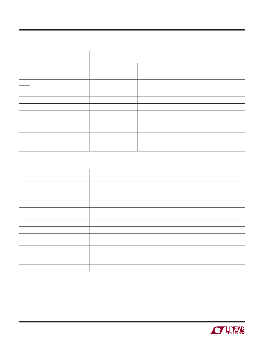
V
OS
Input Offset Voltage
20
50
30
80
µV
LT1006S8
80
400
µV
V
OS
Long-Term Input Offset
0.4
0.5
µV/Mo
Time
Voltage Stability
LT1006S8
0.7
µV/Mo
I
OS
Input Offset Current
0.12
0.5
0.15
0.9
nA
I
B
Input Bias Current
9
15
10
25
nA
e
n
Input Noise Voltage
0.1Hz to 10Hz
0.55
0.55
µV
P-P
Input Noise Voltage Density
f
O
= 10Hz
23
32
23
32
nV/Hz
f
O
= 1000Hz
22
25
22
25
nV/Hz
i
n
Input Noise Current Density
f
O
= 10Hz
0.07
0.08
pA/Hz
Input Resistance
(Note 2)
Differential Mode
180
400
100
300
M
Common Mode
5
4
G
V
S
= 5V, V
CM
= 0V, V
OUT
= 1.4V, T
A
= 25∞C, unless otherwise noted.
ELECTRICAL CHARACTERISTICS

3
LT1006
1006fa
LT1006AM/AC
LT1006M/C
SYMBOL
PARAMETER
CONDITIONS
MIN
TYP
MAX
MIN
TYP
MAX
UNITS
Input Voltage Range
3.5
3.8
3.5
3.8
V
0
≠ 0.3
0
≠ 0.3
V
CMRR
Common Mode Rejection Ratio
V
CM
= 0V to 3.5V
100
114
97
112
dB
PSRR
Power Supply Rejection Ratio
V
S
= ±2V to ±18V, V
O
= 0V
106
126
103
124
dB
A
VOL
Large-Signal Voltage Gain
V
O
= 0.03V to 4V, R
L
= 10k
1.0
2.5
0.7
2.0
V/µV
V
O
= 0.03V to 3.5V, R
L
= 2k
0.5
2.0
0.3
1.8
V/µV
Maximum Output Voltage Swing
Output Low, No Load
15
25
15
25
mV
Output Low, 600 to GND
5
10
5
10
mV
Output Low, I
SINK
= 1mA
220
350
220
350
mV
Output High, No Load
4.0
4.4
4.0
4.4
V
Output High, 600 to GND
3.4
4.0
3.4
4.0
V
SR
Slew Rate
0.25
0.4
0.25
0.4
V/µs
I
S
Supply Current
R
SET
=
340
520
350
570
µA
R
SET
= 180k Pin 8 to Pin 7 (Note 3)
90
90
µA
Minimum Supply Voltage
2.7
2.7
V
V
S
= 5V, V
CM
= 0V, V
OUT
= 1.4V, T
A
= 25∞C, unless otherwise noted.
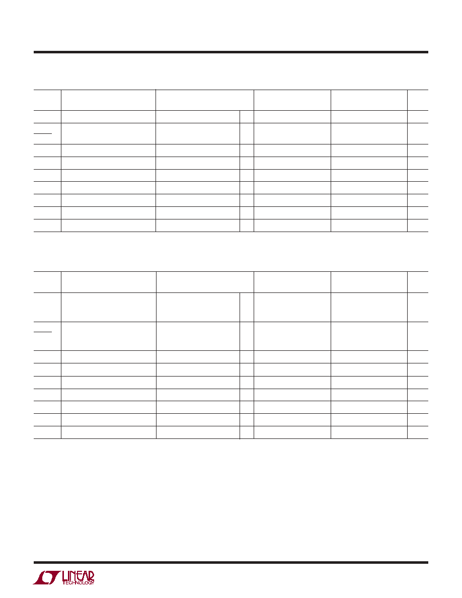
ELECTRICAL CHARACTERISTICS
The
denotes the specifications which apply over the full operating temperature range. V
S
= 5V, 0V; V
CM
= 0.1V; V
O
= 1.4V;
≠55∞C T
A
125∞C, unless otherwise noted.
LT1006AM
LT1006M
SYMBOL
PARAMETER
CONDITIONS
MIN
TYP
MAX
MIN
TYP
MAX
UNITS
V
OS
Input Offset Voltage
40
180
60
250
µV
V
OS
Input Offset Voltage Drift
0.2
1.3
0.3
1.8
µV/∞C
Temp
I
OS
Input Offset Current
0.4
2.0
0.5
4.0
nA
I
B
Input Bias Current
13
25
16
40
nA
A
VOL
Large-Signal Voltage Gain
V
O
= 0.05V to 3.5V, R
L
= 2k
0.25
0.8
0.15
0.7
V/µV
CMRR
Common Mode Rejection Ratio
V
CM
= 0.1V to 3.2V
90
103
87
102
dB
PSRR
Power Supply Rejection Ratio
V
S
= ±2V to ±18V, V
O
= 0V
100
117
97
116
dB
Maximum Output Voltage Swing
Output Low, 600 to GND
6
15
6
18
mV
Output High, 600 to GND
3.2
3.8
3.1
3.8
V
I
S
Supply Current
380
630
400
680
µA
4
LT1006
1006fa
The
denotes the specifications which apply over the full operating
temperature range. V
S
= 5V, 0V; V
CM
= 0V; V
O
= 1.4V; 0∞C T
A
70∞C, unless otherwise noted.
ELECTRICAL CHARACTERISTICS
LT1006AM/AC
LT1006M/C
SYMBOL
PARAMETER
CONDITIONS
MIN
TYP
MAX
MIN
TYP
MAX
UNITS
V
OS
Input Offset Voltage
30
100
50
180
µV
LT1006S8
100
525
µV
I
OS
Input Offset Current
0.1
0.5
0.15
0.9
nA
I
B
Input Bias Current
7.5
12.0
8
20
nA
Input Voltage Range
13.5
13.8
13.5
13.8
V
≠15.0
≠15.3
≠15.0
≠15.3
V
CMRR
Common Mode Rejection Ratio
V
CM
= +13.5V, ≠15V
100
117
97
116
dB
PSRR
Power Supply Rejection Ratio
V
S
= ±2V to ±18V, V
O
= 0V
106
126
103
124
dB
A
VOL
Large Signal Voltage Gain
V
O
= ±10V, R
L
= 2k
1.5
5.0
1.2
4.0
V/µV
V
O
= ±10V, R
L
= 600
0.8
1.5
0.5
1.0
V/µV
V
OUT
Maximum Output Voltage Swing
R
L
= 2k
±13
±14
±12.5
±14
V
SR
Slew Rate
R
SET
=
0.25
0.4
0.25
0.4
V/µs
R
SET
= 390 Pin 8 to Pin 4
1.0
1.2
1.0
1.2
V/µs
I
S
Supply Current
360
540
360
600
µA
V
S
= ±15V, T
A
= 25∞C, unless otherwise noted.
LT1006AC
LT1006C
SYMBOL
PARAMETER
CONDITIONS
MIN
TYP
MAX
MIN
TYP
MAX
UNITS
V
OS
Input Offset Voltage
J8/H Package
30
110
45
160
µV
N8 Package
50
190
µV
S8 Package
110
560
µV
V
OS
Input Offset Voltage Drift
J8/H Package
0.2
1.3
0.3
1.8
µV/∞C
Temp
N8 Package
0.5
2.5
µV/∞C
S8 Package
0.7
3.5
µV/∞C
I
OS
Input Offset Current
0.25
1.2
0.3
2.5
nA
I
B
Input Bias Current
11
20
12
30
nA
A
VOL
Large-Signal Voltage Gain
V
O
= 0.04V to 3.5V, R
L
= 2k
0.35
1.3
0.25
1.2
V/µV
CMRR
Common Mode Rejection Ratio
V
CM
= 0V to 3.4V
96
109
92
108
dB
PSRR
Power Supply Rejection Ratio
V
S
= ±2V to ±18V, V
O
= 0V
101
120
97
118
dB
Maximum Output Voltage Swing
Output Low, 600 to GND
6
13
6
13
mV
Output High, 600 to GND
3.3
3.9
3.2
3.9
V
I
S
Supply Current
350
570
360
620
µA
5
LT1006
1006fa
The
denotes the specifications which apply over the full operating
temperature range. V
S
= ±15V, ≠55∞C T
A
125∞C, unless otherwise noted.
The
denotes the specifications which apply over the full operating temperature range. V
S
= ±15V, 0∞C T
A
70∞C, unless otherwise
noted.
Note 1: Absolute Maximum Ratings are those values beyond which the life
of a device may be impaired.
Note 2: This parameter is guaranteed by design and is not tested.
Note 3: Regular operation does not require an external resistor. In order
to program the supply current for low power or high speed operation,
connect an external resistor from Pin 8 to Pin 7 or from Pin 8 to Pin 4,
respectively. Supply current specifications (for R
SET
= 180k) do not include
current in R
SET
.
Note 4: Optional offset nulling is accomplished with a potentiometer
connected between the trim terminals and the wiper to V
≠
. A 10k pot
(providing a null range of ±6mV) is recommended for minimum drift of
nulled offset voltage with temperature. For increased trim resolution and
accuracy, two fixed resistors can be used in conjunction with a smaller
potentiometer. For example, two 4.7k resistors tied to Pins 1 and 5, with a
500 pot in the middle, will have a null range of ±150µV.
ELECTRICAL CHARACTERISTICS
LT1006AM
LT1006M
SYMBOL
PARAMETER
CONDITIONS
MIN
TYP
MAX
MIN
TYP
MAX
UNITS
V
OS
Input Offset Voltage
80
320
110
460
µV
V
OS
Input Offset Voltage Drift
0.5
2.2
0.6
2.8
µV/∞C
Temp
I
OS
Input Offset Current
0.2
2.0
0.3
3.0
nA
I
B
Input Bias Current
9
18
11
27
nA
A
VOL
Large-Signal Voltage Gain
V
O
= ±10V, R
L
= 2k
0.5
1.5
0.25
1.0
V/µV
CMRR
Common Mode Rejection Ratio
V
CM
= +13V, ≠14.9V
97
114
94
113
dB
PSRR
Power Supply Rejection Ratio
V
S
= ±2V to ±18V, V
O
= 0V
100
117
97
116
dB
Maximum Output Voltage Swing
R
L
= 2k
±12
±13.8
±11.5
±13.8
V
I
S
Supply Current
400
650
400
750
µA
LT1006AC
LT1006C
SYMBOL
PARAMETER
CONDITIONS
MIN
TYP
MAX
MIN
TYP
MAX
UNITS
V
OS
Input Offset Voltage
J8/H Package
50
200
75
300
µV
N8 Package
80
330
µV
S8 Package
150
730
µV
V
OS
Input Offset Voltage Drift
J8/H Package
0.5
2.2
0.6
2.8
µV/∞C
Temp
N8 Package
0.7
3.5
µV/∞C
S8 Package
1.0
4.5
µV/∞C
I
OS
Input Offset Current
0.15
1
0.25
2
nA
I
B
Input Bias Current
8
15
10
23
nA
A
VOL
Large-Signal Voltage Gain
V
O
= ±10V, R
L
= 2k
1
3
0.7
2.5
V/µV
CMRR
Common Mode Rejection Ratio
V
CM
= 13V, ≠15V
98
116
94
114
dB
PSRR
Power Supply Rejection Ratio
V
S
= ±2V to ±18V, V
O
= 0V
101
120
97
118
dB
Maximum Output Voltage Swing
R
L
= 2k
±12.5
±13.9
±11.5
±13.8
V
I
S
Supply Current
370
600
380
660
µA