
1
LT1389
Nanopower Precision
Shunt Voltage Reference
s
Initial Voltage Accuracy: 0.05%
s
Low Operating Current: 800nA
s
Low Drift: 10ppm/
∞
C Max
s
Less Than 1
Dynamic Impedance
s
Available in 1.25V, 2.5V, 4.096V and
5V SO-8 Packages
The LT
Æ
1389 is a nanopower, precision shunt voltage
reference. The bandgap reference uses trimmed preci-
sion thin-film resistors and improved curvature correction
techniques to achieve 0.05% initial voltage accuracy with
guaranteed 10ppm/
∞
C maximum temperature drift. Volt-
age regulation is maintained to an ultralow 800nA operating
current. Advances in design, processing and packaging
achieve low temperature cycling hysteresis.
The LT1389 does not require an output compensation
capacitor, but is stable with capacitive loads. Low dy-
namic impedance makes the LT1389 reference easy to
use from unregulated supplies.
The LT1389 reference can be used as a high performance
upgrade to the LM185/LM385, LT1004, LT1034 and
LT1634 where lowest power and guaranteed tempera-
ture drift are required.
s
Portable Meters
s
Precision Regulators
s
A/D and D/A Converters
s
Calibrators
5V
4.7M
LT1389-1.25
1389 TA01
V
OUT
1.25V
TEMPERATURE (
∞
C)
0
REFERENCE VOLTAGE CHANGE (mV)
1.5
30
1389 TA02
0
≠1.0
10
20
40
≠1.5
≠ 2.0
2.0
1.0
0.5
≠ 0.5
50
60
70
I
R
= 0.8
µ
A
V
OUT
= 1.25V
Temperature Drift
, LTC and LT are registered trademarks of Linear Technology Corporation.
DESCRIPTIO
U
FEATURES
APPLICATIO S
U
TYPICAL APPLICATIO
U
2
LT1389
OUTPUT
TEMPERATURE COEFFICIENT
TEMPERATURE
VOLTAGE
ACCURACY (%)
(ppm/
∞
C)
PART TYPE
PART MARKING
0
∞
C to 70
∞
C
1.250
0.05
10
LT1389ACS8-1.25
389A12
1.250
0.05
20
LT1389BCS8-1.25
389B12
2.500
0.05
20
LT1389BCS8-2.5
389B25
4.096
0.075
50
LT1389BCS8-4.096
1389B4
5.000
0.075
50
LT1389BCS8-5
1389B5
ORDER PART
NUMBER
(Note 1)
Operating Current
1.25V ............................................................... 20mA
2.5V ................................................................. 20mA
4.096V ............................................................. 10mA
5V .................................................................... 10mA
Forward Current .................................................. 20mA
Operating Temperature Range ..................... 0
∞
C to 70
∞
C
Storage Temperature Range (Note 2) ... ≠ 65
∞
C to 150
∞
C
Lead Temperature (Soldering, 10 sec).................. 300
∞
C
S8 PART MARKING
LT1389ACS8-1.25
LT1389BCS8-1.25
LT1389BCS8-2.5
LT1389BCS8-4.096
LT1389BCS8-5
389A12
389B12
389B25
*Connected internally. Do Not Connect external circuitry to these pins.
Consult factory for Industrial and Military grade parts.
T
JMAX
= 125
∞
C,
JA
= 190
∞
C/ W
1
2
3
4
8
7
6
5
TOP VIEW
S8 PACKAGE
8-LEAD PLASTIC SO
DNC*
DNC*
DNC*
GND
DNC*
DNC*
V
OUT
GND
AVAILABLE OPTIO S
U
The
q
denotes specifications which apply over the full operating
temperature range, otherwise specifications are at T
A
= 25
∞
C. (Note 3)
PARAMETER
CONDITIONS
MIN
TYP
MAX
UNITS
Reverse Breakdown Voltage
LT1389ACS8/LT1389BCS8 (I
R
= 0.8
µ
A)
1.24937
1.250
1.25062
V
≠ 0.05
0.05
%
LT1389ACS8 (I
R
= 0.8
µ
A)
q
1.24849
1.250
1.25149
V
≠ 0.12
0.12
%
LT1389BCS8 (I
R
= 0.8
µ
A)
q
1.24762
1.250
1.25237
V
≠ 0.19
0.19
%
Reverse Breakdown Change
0.8
µ
A
I
R
200
µ
A
0.20
0.4
mV
with Current (Note 4)
q
0.20
1.0
mV
200
µ
A
I
R
2mA
0.3
1.0
mV
q
0.3
2.0
mV
Minimum Operating Current
q
0.6
µ
A
Temperature Coefficient
LT1389ACS8 (I
R
= 0.8
µ
A)
q
4
10
ppm/
∞
C
LT1389BCS8 (I
R
= 0.8
µ
A)
q
4
20
ppm/
∞
C
Reverse Dynamic Impedance (Note 5)
0.8
µ
A
I
R
2mA
0.25
0.7
q
0.25
1.5
Low Frequency Noise (Note 6)
I
R
= 0.8
µ
A, 0.1Hz
f
10Hz
25
µ
V
P-P
1.25V ELECTRICAL CHARACTERISTICS
1389B4
1389B5
PACKAGE/ORDER I FOR ATIO
U
U
W
ABSOLUTE AXI U RATI GS
W
W
W
U

3
LT1389
PARAMETER
CONDITIONS
MIN
TYP
MAX
UNITS
Reverse Breakdown Voltage
LT1389BCS8 (I
R
= 0.9
µ
A)
2.49875
2.500
2.50125
V
≠ 0.05
0.05
%
LT1389BCS8 (I
R
= 0.9
µ
A)
q
2.49525
2.500
2.50475
V
≠ 0.19
0.19
%
Reverse Breakdown Change
0.9
µ
A
I
R
200
µ
A
0.2
0.5
mV
with Current (Note 4)
q
0.2
1.5
mV
200
µ
A
I
R
2mA
0.3
1.0
mV
q
0.3
2.5
mV
Minimum Operating Current
q
0.7
µ
A
Temperature Coefficient
I
R
= 0.9
µ
A
q
8
20
ppm/
∞
C
Reverse Dynamic Impedance (Note 5)
0.9
µ
A
I
R
2mA
0.25
0.75
q
0.25
2
Low Frequency Noise (Note 6)
I
R
= 0.9
µ
A, 0.1Hz
f
10Hz
50
µ
V
P-P
2.5V ELECTRICAL CHARACTERISTICS
The
q
denotes specifications which apply over the full operating
temperature range, otherwise specifications are at T
A
= 25
∞
C. (Note 3)
PARAMETER
CONDITIONS
MIN
TYP
MAX
UNITS
Reverse Breakdown Voltage
LT1389BCS8 (I
R
= 1.5
µ
A)
4.09293
4.096
4.09907
V
≠ 0.075
0.075
%
LT1389BCS8 (I
R
= 1.5
µ
A)
q
4.0788
4.096
4.1132
V
≠ 0.42
0.42
%
Reverse Breakdown Change
1.5
µ
A
I
R
200
µ
A
0.2
1.5
mV
with Current (Note 4)
q
0.2
3
mV
200
µ
A
I
R
2mA
0.3
4
mV
q
0.3
6
mV
Minimum Operating Current
q
1
µ
A
Temperature Coefficient
I
R
= 1.5
µ
A
q
12
50
ppm/
∞
C
Reverse Dynamic Impedance (Note 5)
1.5
µ
A
I
R
2mA
0.75
2
q
0.75
3
Low Frequency Noise (Note 6)
I
R
= 1.5
µ
A, 0.1Hz
f
10Hz
80
µ
V
P-P
4.096V ELECTRICAL CHARACTERISTICS
The
q
denotes specifications which apply over the full
operating temperature range, otherwise specifications are at T
A
= 25
∞
C. (Note 3)
4
LT1389
PARAMETER
CONDITIONS
MIN
TYP
MAX
UNITS
Reverse Breakdown Voltage
LT1389BCS8 (I
R
= 1.5
µ
A)
4.99625
5.000
5.00375
V
≠ 0.075
0.075
%
LT1389BCS8 (I
R
= 1.5
µ
A)
q
4.979
5.000
5.021
V
≠ 0.42
0.42
%
Reverse Breakdown Change
1.5
µ
A
I
R
200
µ
A
0.2
1.5
mV
with Current (Note 4)
q
0.2
3
mV
200
µ
A
I
R
2mA
0.3
4
mV
q
0.3
6
mV
Minimum Operating Current
q
1
µ
A
Temperature Coefficient
I
R
= 1.5
µ
A
q
12
50
ppm/
∞
C
Reverse Dynamic Impedance (Note 5)
1.5
µ
A
I
R
2mA
0.75
2
q
0.75
3
Low Frequency Noise (Note 6)
I
R
= 1.5
µ
A, 0.1Hz
f
10Hz
100
µ
V
P-P
5V ELECTRICAL CHARACTERISTICS
The
q
denotes specifications which apply over the full operating
temperature range, otherwise specifications are at T
A
= 25
∞
C. (Note 3)
Note 1: Absolute Maximum Ratings are those values beyond which the life
of a device may be impaired.
Note 2: If the part is stored outside of the specific operating temperature
range, the output may shift due to hysteresis.
Note 3: ESD (Electrostatic Discharge) sensitive device. Use proper ESD
handling precautions.
Note 4: Output requires 0.1
µ
F for operating current greater than 1mA.
Note 5: This parameter is guaranteed by "reverse breakdown change with
current" test.
Note 6: Peak-to-peak noise is measured with a single highpass filter at
0.1Hz and 2-pole lowpass filter at 10Hz.
5
LT1389
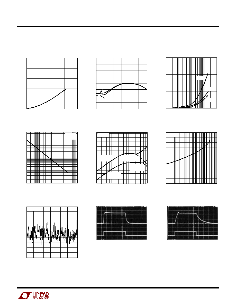
Reverse Characteristics
Reverse Voltage Change
vs Current
Dynamic Impedance vs Frequency
Forward Characteristics
Reverse Dynamic Impedance
0.1Hz to 10Hz Noise
200ms/DIV
I
R
= 0.8
µ
A
C
OUT
= 0.1
µ
F
Response Time
0V
1ms/DIV
1389-1.25 G08
0V
Response Time
REVERSE VOLTAGE (V)
0
REVERSE CURRENT (
µ
A)
0.4
0.6
1.6
1389-1.25 G01
0.2
0
0.4
0.8
1.2
1.0
0.8
T
A
= ≠ 40
∞
C TO 85
∞
C
TEMPERATURE (
∞
C)
≠ 40
REFERENCE VOLTAGE CHANGE (mV)
1.5
20
1389-1.25 G02
0
≠1.0
≠20
0
40
≠1.5
≠ 2.0
2.0
1.0
0.5
≠ 0.5
60
80
I
R
= 250
µ
A
I
R
= 0.8
µ
A
Temperature Drift
FREQUENCY (kHz)
0.1
DYNAMIC IMPEDANCE (k
)
1
10
100
0.1
1
10
1389-1.25 G05
0.01
0.01
I
R
= 0.8
µ
A
C
OUT
= 0
µ
F
I
R
= 0.8
µ
A
C
OUT
= 0.047
µ
F
I
R
= 10
µ
A
C
OUT
= 0.1
µ
F
I
R
= 10
µ
A
C
OUT
= 0
µ
F
T
A
= 25
∞
C
TIME (SEC)
0
NOISE VOLTAGE (
µ
V/DIV)
5
15
25
40
1389-1.25 G07
≠ 5
≠15
0
10
20
≠10
≠ 20
≠ 25
10
20
30
50
70
60
I
R
= 0.8
µ
A
1.25V TYPICAL PERFOR A CE CHARACTERISTICS
U
W
1.5V
1V
0.5V
5V
I
R
= 0.8
µ
A
C
OUT
= 0
µ
F
1.5V
1V
0.5V
0V
5V
0V
1389-1.25 G09
FORWARD CURRENT (mA)
0.001
0.4
FORWARD VOLTAGE (V)
0.5
0.6
0.7
0.8
0.01
0.1
1
10
100
1389-1.25 G06
0.3
0.2
0.1
0
0.9
1.0
T
A
= 25
∞
C
REVERSE CURRENT (mA)
0.001
0.1
DYNAMIC IMPEDANCE (
)
10
1000
0.1
0.01
10
1
1389-1.25 G04
1
100
T
A
= 25
∞
C
f = 25Hz
REVERSE CURRENT (mA)
0.4
REVERSE VOLTAGE CHANGE (mV)
0.8
1.2
0.001
0.1
10
1
1389-1.25 G03
0
0.6
1.0
0.2
0.01
25
∞
C
85
∞
C
≠ 40
∞
C