 | ÐлекÑÑоннÑй компоненÑ: LT1723IS8 | СкаÑаÑÑ:  PDF PDF  ZIP ZIP |
Äîêóìåíòàöèÿ è îïèñàíèÿ www.docs.chipfind.ru
LT1722/LT1723/LT1724
1
172234fa
s
Video and RF Amplification
s
ADSL, HDSL II, VDSL Receivers
s
Active Filters
s
Wideband Amplifiers
s
Buffers
s
Data Acquisition Systems
s
3.8nV/
Hz Input Noise Voltage
s
3.7mA Supply Current
s
200MHz Gain Bandwidth
s
Low Total Harmonic Distortion: 85dBc at 1MHz
s
70V/
µ
s Slew Rate
s
400
µ
V Maximum Input Offset Voltage
s
300nA Maximum Input Bias Current
s
Unity-Gain Stable
s
Capacitive Load Stable Up to 100pF
s
23mA Minimum Output Current
s
Specified at
±
5V and Single 5V
Single, Dual, Quad 200MHz
Low Noise Precision Op Amps
The LT
®
1722/LT1723/LT1724 are single/dual/quad, low
noise, low power, high speed operational amplifiers. These
products feature lower input offset voltage, lower input
bias current and higher DC gain than devices with compa-
rable bandwidth. The 200MHz gain bandwidth ensures
high open-loop gain at video frequencies.
The low input noise voltage is achieved with reduced
supply current. The total noise is optimized for a source
resistance between 0.8k and 12k. Due to the input bias
current cancellation technique used, the resistance seen
by each input does not need to be balanced.
The output drives a 150
load to
±
3V with
±
5V supplies.
On a single 5V supply the output swings from 1.5V to 3.5V
with a 500
load connected to 2.5V. The amplifier is unity-
gain stable (C
LOAD
100pF).
The LT1722/LT1723/LT1724 are manufactured on Linear
Technology's advanced low voltage complementary
bipolar process. The LT1722 is available in the SO-8 and
5-pin SOT-23 packages. The LT1723 is available in the
SO-8 and MS8 packages. The LT1724 is available in the
14-lead SO package.
, LTC and LT are registered trademarks of Linear Technology Corporation.
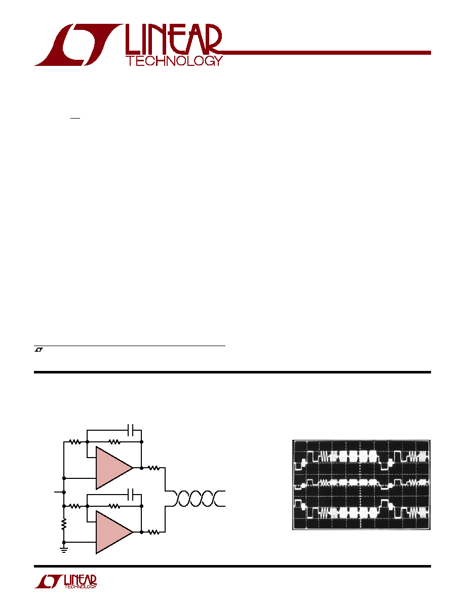
+
1/2 LT1723
R5 2k
R3
750
R7
62.5
+V
OUT
V
IN
/2 62.5
LOAD
62.5
LOAD
V
IN
/2
V
IN
1723 TA01
V
IN
V
OUT
125
CAT-5
TWISTED PAIR
C1 5pF
+
1/2 LT1723
R4 2k
V
IN
75
SOURCE
R2
2k
R1
75
R6
62.5
C2 5pF
Differential Video Line Driver
Line Driver Mulitburst Video Signal
+V
OUT
0.5V/DIV
1723 TA02
V
IN
1V/DIV
V
OUT
0.5V/DIV
DESCRIPTIO
U
FEATURES
APPLICATIO S
U
TYPICAL APPLICATIO
U
LT1722/LT1723/LT1724
2
172234fa
Total Supply Voltage (V
+
to V
) ............................ 12.6V
Input Voltage ...........................................................
±
V
S
Differential Input Voltage (Note 2) ........................
±
0.7V
Input Current (Note 2) ........................................
±
10mA
Output Short-Circuit Duration (Note 3) ............ Indefinite
T
JMAX
= 150
°
C,
JA
= 190
°
C/W
ABSOLUTE AXI U
RATI GS
W
W
W
U
PACKAGE/ORDER I FOR ATIO
U
U
W
(Note 1)
Consult LTC Marketing for parts specified with wider operating temperature ranges.
*The temperature grades are identified by a label on the shipping container.
Operating Temperature Range (Note 4) ... 40
°
C to 85
°
C
Specified Temperature Range (Note 5) ... 40
°
C to 85
°
C
Maximum Junction Temperature .......................... 150
°
C
Storage Temperature Range ................. 65
°
C to 150
°
C
Lead Temperature (Soldering, 10 sec)................. 300
°
C
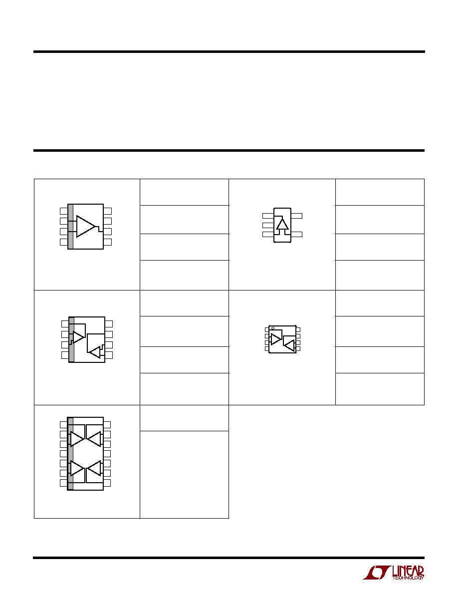
ORDER PART
NUMBER
LT1722CS8
LT1722IS8
ORDER PART
NUMBER
S5 PART
MARKING*
LTZB
LT1722CS5
LT1722IS5
T
JMAX
= 150
°
C,
JA
= 250
°
C/W
1722
1722I
S8 PART
MARKING
TOP VIEW
V
+
OUT B
IN B
+IN B
OUT A
IN A
+IN A
V
S8 PACKAGE
8-LEAD PLASTIC SO
1
2
3
4
8
7
6
5
A
B
TOP VIEW
NC
V
+
OUT
NC
NC
IN
+IN
V
S8 PACKAGE
8-LEAD PLASTIC SO
1
2
3
4
8
7
6
5
+
T
JMAX
= 150
°
C,
JA
= 150
°
C/W
OUT 1
V
2
TOP VIEW
S5 PACKAGE
5-LEAD PLASTIC SOT-23
+IN 3
5 V
+
4 IN
+
ORDER PART
NUMBER
LT1723CS8
LT1723IS8
1723
1723I
S8 PART
MARKING
T
JMAX
= 150
°
C,
JA
= 100
°
C/W
ORDER PART
NUMBER
LT1724CS
LT1724IS
TOP VIEW
S PACKAGE
14-LEAD PLASTIC SO
1
2
3
4
5
6
7
14
13
12
11
10
8
8
OUT A
IN A
+IN A
V
+
+IN B
IN B
OUT B
OUT D
IN D
+IN D
V
+IN C
IN C
OUT C
+
+
A
D
+
+
B
C
ORDER PART
NUMBER
LT1723CMS8
LT1723IMS8
LTYC
LTZA
MS8 PART
MARKING
1
2
3
4
OUT A
IN A
+IN A
V
8
7
6
5
V
+
OUT B
IN B
+IN B
TOP VIEW
MS8 PACKAGE
8-LEAD PLASTIC MSOP
A
B
T
JMAX
= 150
°
C,
JA
= 250
°
C/W
LT1722/LT1723/LT1724
3
172234fa
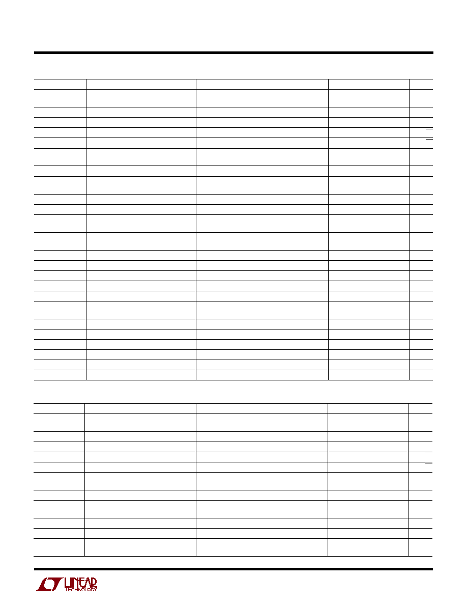
SYMBOL
PARAMETER
CONDITIONS
MIN
TYP
MAX
UNITS
V
OS
Input Offset Voltage
(Note 6)
100
400
µ
V
LT1722 SOT-23 and LT1723 MS8
150
650
µ
V
I
OS
Input Offset Current
40
300
nA
I
B
Input Bias Current
40
300
nA
e
n
Input Noise Voltage
f = 10kHz
3.8
nV/
Hz
i
n
Input Noise Current
f = 10kHz
1.2
pA/
Hz
R
IN
Input Resistance
V
CM
=
±
3.5V
5
35
M
Differential
50
k
C
IN
Input Capacitance
2
pF
Input Voltage Range +
3.5
4
V
Input Voltage Range
4
3.5
V
CMRR
Common Mode Rejection Ratio
V
CM
=
±
3.5V
80
100
dB
PSRR
Power Supply Rejection Ratio
V
S
=
±
2.3V to
±
5.5V
78
90
dB
A
VOL
Large-Signal Voltage Gain
V
OUT
=
±
3V, R
L
= 500
10
17
V/mV
V
OUT
=
±
3V, R
L
= 150
7
14
V/mV
V
OUT
Output Swing
R
L
= 500
, V
IN
=
±
10mV
±
3.2
±
3.8
V
R
L
= 150
, V
IN
=
±
10mV
±
3.1
±
3.4
V
I
OUT
Output Current
V
OUT
=
±
3V, 10mV Overdrive
23
50
mA
I
SC
Short-Circuit Current
V
OUT
= 0V, V
IN
=
±
1V
35
90
mA
SR
Slew Rate
A
V
= 1, (Note 7)
45
70
V/
µ
s
Full Power Bandwidth
3V peak, (Note 8)
3.7
MHz
GBW
Gain Bandwidth
f = 200kHz
115
200
MHz
t
S
Settling Time
A
V
= 1, 2V, 0.1%
91
ns
A
V
= 1, 2V, 0.01%
112
ns
t
r
, t
f
Rise Time, Fall Time
A
V
= 1, 10% to 90%, V
IN
= 0.2V
P-P
, R
L
= 150
6
ns
Overshoot
A
V
= 1, V
IN
= 0.2V
P-P
, R
L
= 150
, R
F
= 0
15
%
Propagation Delay
50% V
IN
to 50% V
OUT
= 0.2V
P-P
, R
L
= 150
3
ns
R
O
Output Resistance
A
V
= 1, f = 1MHz
0.15
Channel Separation
V
OUT
=
±
3V, R
L
= 150
82
90
dB
I
S
Supply Current
Per Amplifier
3.7
4.5
mA
T
A
= 25
°
C, V
S
=
±
5V, V
CM
= 0V, unless otherwise noted.
ELECTRICAL CHARACTERISTICS
T
A
= 25
°
C. V
S
= 5V, V
CM
= 2.5V, R
L
to 2.5V, unless otherwise noted.
SYMBOL
PARAMETER
CONDITIONS
MIN
TYP
MAX
UNITS
V
OS
Input Offset Voltage
(Note 6)
250
550
µ
V
LT1722 SOT-23 and LT1723 MS8
350
800
µ
V
I
OS
Input Offset Current
20
300
nA
I
B
Input Bias Current
20
300
nA
e
n
Input Noise Voltage
f = 10kHz
4
nV/
Hz
i
n
Input Noise Current
f = 10kHz
1.1
pA/
Hz
R
IN
Input Resistance
V
CM
= 1.5V to 3.5V
5
32
M
Differential
55
k
C
IN
Input Capacitance
2
pF
Input Voltage Range +
3.5
4
V
Input Voltage Range
1
1.5
V
CMRR
Common Mode Rejection Ratio
V
CM
= 1.5V to 3.5V
80
100
dB
A
VOL
Large-Signal Voltage Gain
V
OUT
= 1.5V to 3.5V, R
L
= 500
4
10
V/mV
V
OUT
Output Swing+
R
L
= 500
, V
IN
=
±
10mV
3.6
3.8
V
Output Swing
R
L
= 500
, V
IN
=
±
10mV
0.9
1.4
V
LT1722/LT1723/LT1724
4
172234fa
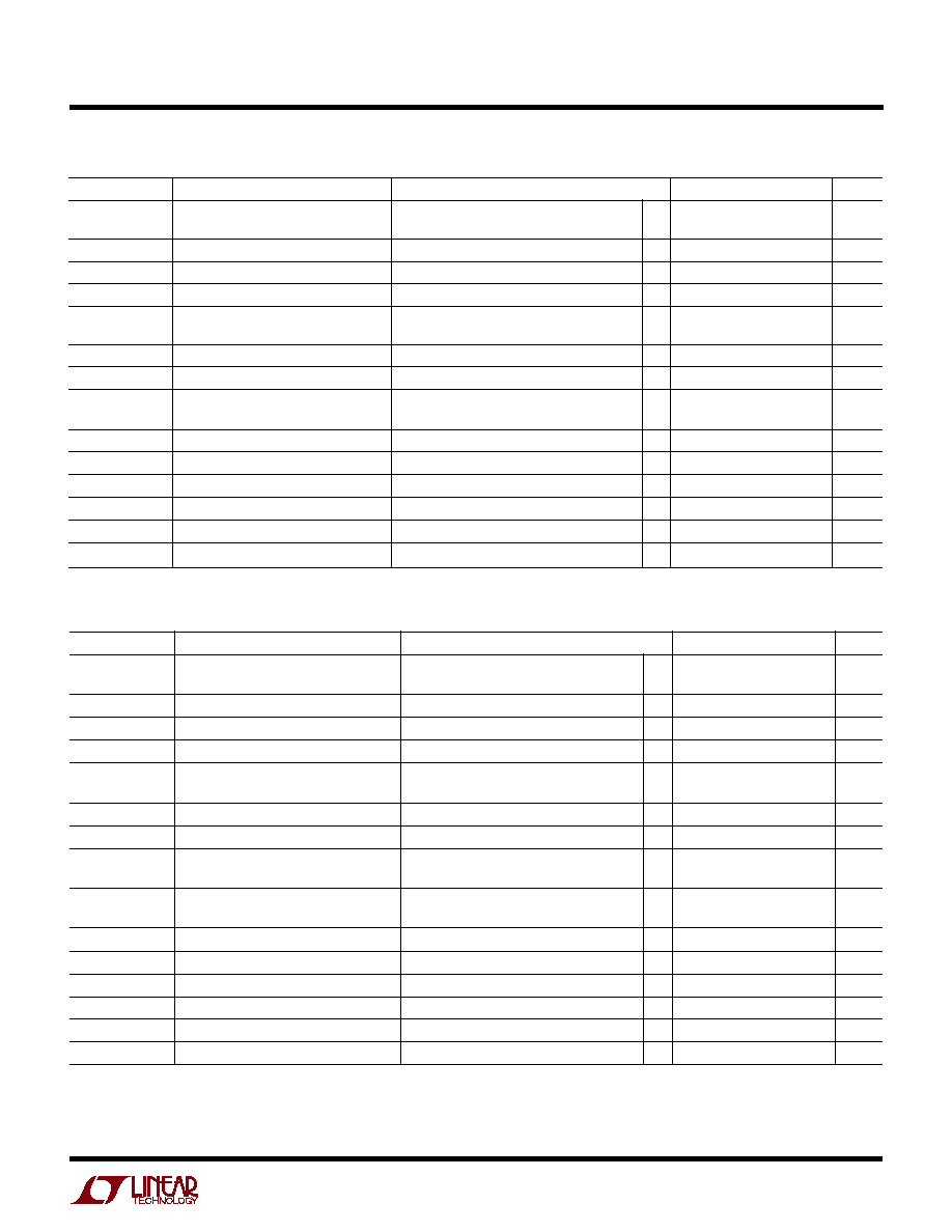
The
q
denotes the specifications which apply over the temperature range of 0
°
C
T
A
70
°
C. V
S
=
±
5V, V
CM
= 0V,
unless otherwise noted. (Note 5)
SYMBOL
PARAMETER
CONDITIONS
MIN
TYP
MAX
UNITS
V
OS
Input Offset Voltage
(Note 6)
q
700
µ
V
LT1722 SOT-23 and LT1723 MS8
q
850
µ
V
Input V
OS
Drift
(Note 9)
q
3
7
µ
V/
°
C
I
OS
Input Offset Current
q
350
nA
I
B
Input Bias Current
q
350
nA
Input Voltage Range +
q
3.5
V
Input Voltage Range
q
3.5
V
CMRR
Common Mode Rejection Ratio
V
CM
=
±
3.5V
q
75
dB
PSRR
Power Supply Rejection Ratio
V
S
=
±
2.3V to
±
5.5V
q
76
dB
A
VOL
Large-Signal Voltage Gain
V
OUT
=
±
3V, R
L
= 500
q
9
V/mV
V
OUT
=
±
3V, R
L
= 150
q
6
V/mV
V
OUT
Output Swing
R
L
= 500
, V
IN
=
±
10mV
q
±
3.15
V
R
L
= 150
, V
IN
=
±
10mV
q
±
3.05
V
I
OUT
Output Current
V
OUT
=
±
3V, 10mV Overdrive
q
22
mA
I
SC
Short-Circuit Current
V
OUT
= 0V, V
IN
=
±
1V
q
30
mA
SR
Slew Rate
A
V
= 1, (Note 7)
q
35
V/
µ
s
GBW
Gain Bandwidth
f = 200kHz
q
100
MHz
Channel Separation
V
OUT
=
±
3V, R
L
= 150
q
81
dB
I
S
Supply Current
Per Amplifier
q
5.45
mA
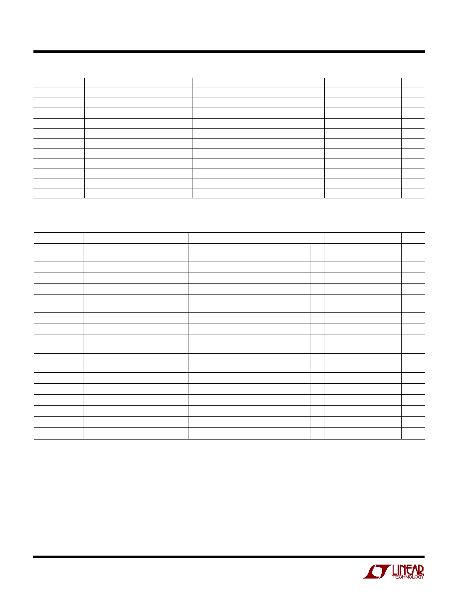
SYMBOL
PARAMETER
CONDITIONS
MIN
TYP
MAX
UNITS
I
OUT
Output Current
V
OUT
= 3.5V or 1.5V, 10mV Overdrive
10
20
mA
I
SC
Short-Circuit Current
V
OUT
= 2.5V, V
IN
=
±
1V
22
55
mA
SR
Slew Rate
A
V
= -1, (Note 7)
40
70
V/
µ
s
Full Power Bandwidth
1V peak, (Note 8)
8.7
MHz
GBW
Gain Bandwidth (Note 10)
f = 200kHz
115
180
MHz
t
r
, t
f
Rise Time, Fall Time
A
V
= 1, 10% to 90%, V
IN
= 0.2V
P-P
, R
L
= 500
5
ns
Overshoot
A
V
= 1, V
IN
= 0.2V
P-P
, R
L
= 500
16
%
Propagation Delay
50% V
IN
to 50% V
OUT
, 0.1V, R
L
= 500
3
ns
R
O
Output Resistance
A
V
= 1, f = 1MHz
0.19
Channel Separation
V
OUT
= 1.5V to 3.5V, R
L
= 500
82
90
dB
I
S
Supply Current
Per Amplifier
3.8
5
mA
T
A
= 25
°
C. V
S
= 5V, V
CM
= 2.5V, R
L
to 2.5V, unless otherwise noted.
ELECTRICAL CHARACTERISTICS
LT1722/LT1723/LT1724
5
172234fa
ELECTRICAL CHARACTERISTICS
The
q
denotes the specifications which apply over the temperature range of 40
°
C
T
A
85
°
C. V
S
=
±
5V, V
CM
= 0V,
unless otherwise noted. (Note 5)
SYMBOL
PARAMETER
CONDITIONS
MIN
TYP
MAX
UNITS
V
OS
Input Offset Voltage
(Note 6)
q
900
µ
V
LT1722 SOT-23 and LT1723 MS8
q
1100
µ
V
Input V
OS
Drift
(Note 9)
q
3
10
µ
V/
°
C
I
OS
Input Offset Current
q
400
nA
I
B
Input Bias Current
q
400
nA
Input Voltage Range +
q
3.5
V
Input Voltage Range
3.5
V
CMRR
Common Mode Rejection Ratio
V
CM
=
±
3.5V
q
75
dB
PSRR
Power Supply Rejection Ratio
V
S
=
±
2.0V to
±
5.5V
q
75
dB
A
VOL
Large-Signal Voltage Gain
V
OUT
=
±
3V, R
L
= 500
q
8
V/mV
V
OUT
=
±
3V, R
L
= 150
q
5
V/mV
V
OUT
Output Swing
R
L
= 500
, V
IN
=
±
10mV
q
±
3.1
V
R
L
= 150
, V
IN
=
±
10mV
q
±
3.0
V
I
OUT
Output Current
V
OUT
=
±
3V, 10mV Overdrive
q
20
mA
I
SC
Short-Circuit Current
V
OUT
= 0V, V
IN
=
±
1V
q
25
mA
SR
Slew Rate
A
V
= 1, (Note 7)
q
25
V/
µ
s
GBW
Gain Bandwidth
f = 200kHz
q
90
MHz
Channel Separation
V
OUT
=
±
3V, R
L
= 150
q
80
dB
I
S
Supply Current
q
5.95
mA
SYMBOL
PARAMETER
CONDITIONS
MIN
TYP
MAX
UNITS
V
OS
Input Offset Voltage
(Note 6)
q
850
µ
V
LT1722 SOT-23 and LT1723MS8
q
950
µ
V
Input V
OS
Drift
(Note 9)
q
3
7
µ
V/
°
C
I
OS
Input Offset Current
q
350
nA
I
B
Input Bias Current
q
350
nA
Input Voltage Range +
q
3.5
V
Input Voltage Range
q
1.5
V
CMRR
Common Mode Rejection Ratio
V
CM
= 1.5V to 3.5V
q
75
dB
A
VOL
Large-Signal Voltage Gain
V
OUT
= 1.5V to 3.5V, R
L
= 500
q
3
V/mV
V
OUT
Output Swing+
R
L
= 500
, V
IN
=
±
10mV
q
3.55
V
Output Swing
R
L
= 500
, V
IN
=
±
10mV
q
1.45
V
I
OUT
Output Current
V
OUT
= 3.5V or 1.5V, 10mV Overdrive
q
9
mA
I
SC
Short-Circuit Current
V
OUT
= 2.5V, V
IN
=
±
1V
q
11
mA
SR
Slew Rate
A
V
= 1, (Note 7)
q
30
V/
µ
s
GBW
Gain Bandwidth (Note 10)
f = 200kHz
q
100
MHz
Channel Separation
V
OUT
= 1.5V to 3.5V, R
L
= 500
q
81
dB
I
S
Supply Current
q
5.95
mA
The
q
denotes the specifications which apply over the temperature range of
0
°
C
T
A
70
°
C. V
S
= 5V, V
CM
= 2.5V, R
L
to 2.5V, unless otherwise noted. (Note 5)