1206L Series
Resettable PTCs
246
w w w . l i t t e l f u s e . c o m
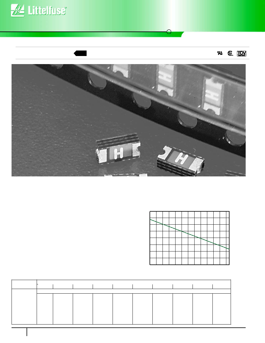
Surface Mount PTC
Temperature Rerating Curve:
-40∞C
-20∞C
0∞C
20∞C
40∞C
50∞C
60∞C
70∞C
80∞C
85∞C
Part Number
1206L020
0.29
0.26
0.23
0.20
0.17
0.16
0.14
0.13
0.11
0.10
1206L025
0.36
0.33
0.29
0.25
0.21
0.20
0.18
0.16
0.14
0.13
1206L035
0.51
0.46
0.40
0.35
0.30
0.27
0.25
0.22
0.20
0.18
1206L050
0.74
0.67
0.59
0.50
0.44
0.40
0.36
0.32
0.28
0.26
1206L075
1.11
1.00
0.89
0.75
0.65
0.59
0.54
0.48
0.42
0.39
1206L110
1.63
1.46
1.30
1.10
0.96
0.87
0.79
0.70
0.62
0.57
1206L150
2.22
2.00
1.77
1.50
1.31
1.19
1.08
0.96
0.84
0.78
Temperature Rerating:
∑ Complies with electronic industry environmental standards for
lead reduction.
PHYSICAL SPECIFICATIONS:
Terminal Material:
Tin Plated Copper
Device Labeling:
Device is marked with amperage rating code.
AGENCY APPROVALS:
Recognized under the Components Program of
Underwriters Laboratories and the Acceptance program of CSA. TUV approved.
AGENCY FILE NUMBERS:
UL E183209, CSA LR108832.
ENVIRONMENTAL SPECIFICATIONS:
Passive Aging: 85∞C, 1000 Hours.
Humidity Aging: 85∞C, 85% R.H., 100 hours.
Thermal Shock: 85∞C / ≠40∞C, 20 times.
Vibration: MIL-STD 202, Method 201, MIL-STD-883, Method 2007.
Mechanical Shock: MIL-STD-202, Method 213 test
condition I (100 g's, 6 sec.).
Solvent Resistance: MIL-STD-202, Method 215.
Operating/Storage Temperature: ≠40∞C to 85∞C
Device should remain in sealed bags prior to use.
Hold Current (A)
Ambient Temperature
Æ
Æ
-40
-30
-20
-10
0
10
20
30
40
50
60
70
80 85
10%
30%
50%
70%
90%
110%
130%
150%
170%
Temperature (
∞C)
Percentage of Rated Current
Packaging:
8mm tape and reel carrier per EIA 481 Standard.
Standard reel quantities: 0.20-0.35A: 4,000 devices on 7" reel (YRT Suffix).
0.50-1.50A: 3,000 devices on 7" reel (WRT Suffix).
NEW
Surface Mount PTC
1206L Series
Resettable PTCs
247
w w w . l i t t e l f u s e . c o m
6
RESETT
ABLE PTCs
Ihold
=
Hold Current: maximum current device will sustain for 4 hours without tripping in 20∞C still air.
Itrip
=
Trip Current: minimum current at which the device will trip in 20∞C still air.
Vmax
=
Maximum voltage device can withstand without damage at rated current (Imax)
Imax
=
Maximum fault current device can withstand without damage at rated voltage (Vmax)
Pd
=
Power dissipated from device when in the tripped state at 20∞C still air.
RIL
=
Minimum resistance of device in initial (un-soldered) state.
RAT
=
Maximum measured resistance in the non-tripped state 1 hour after reflow with reflow conditions of 245∞C for 20 sec.
CAUTION: Operation beyond the specified ratings may result in damage and possible arcing and flame.
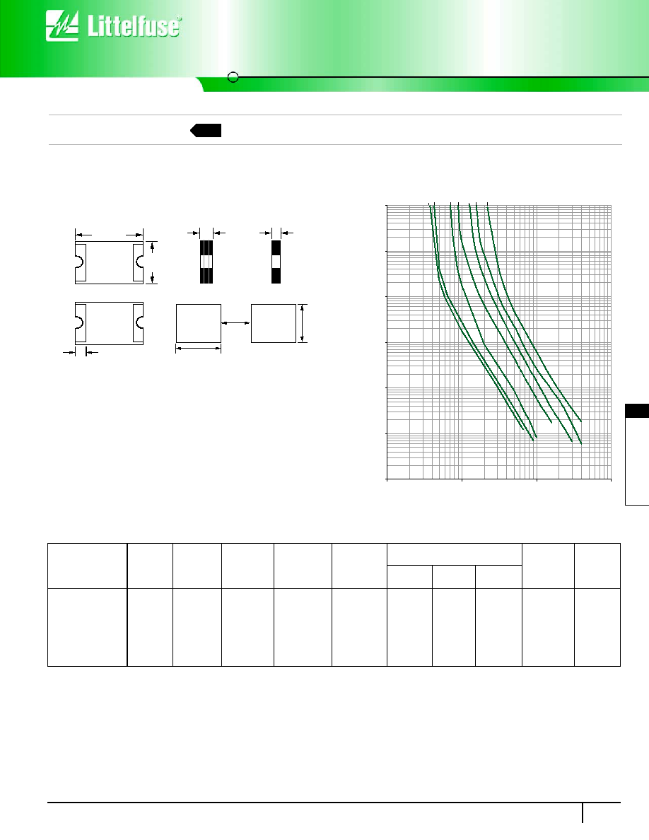
Dimensions (Inches)
3.15 mm (.124)
1.65 mm
(.064)
1.12 mm
(.044)
0.762 mm
(.030)
Top
View
Pad
Layout
Side
View
Side
View
Bottom
View
1.40 mm
(.055)
1.52 mm
(.060)
2.16 mm
(.085)
1206L050
1206L075
1206L110
1206L150
1206L020
1206L025
1206L035
0.64 mm
(.023)
Tin Plated Terminals
H
H
0.5A
0.75A
1.1A
0.25A
0.20A
0.35A
1.5A
100
10
1
0.1
0.01
0.001
TRIP
TIME IN SECONDS
0.1
1
10
100
CURRENT IN AMPERES
0.0001
Average Time Current Curves
Solderability:
Meets EIA specification RS186-9E and IPC/EIA
J-STD-002, and IPC/EIA J-STD-001.
Soldering Parameters:
Reflow Solder -- 245∞C, 20 seconds maximum
Wave Solder -- 245∞C, 10 seconds maximum
Recommended Pad Layout (Inches)
All dimensions are nominal.
Part Marking
I
Hold
I
Trip
V
Max
I
Max
P
d
max. Current
Time
R
IL
R
AT
Number
Code
(A)
(A)
(V
dc
)
(A)
(W)
(A)
(Sec)
(
)
(
)
1206L020
C
0.20
0.40
15.0
40
0.8
8.0
0.05
0.600
2.500
1206L025
D
0.25
0.50
15.0
40
0.8
8.0
0.08
0.550
2.300
1206L035
E
0.35
0.70
6.0
40
0.8
8.0
0.10
0.300
1.300
1206L050
F
0.50
1.00
6.0
40
0.8
8.0
0.10
0.090
0.600
1206L075
G
0.75
1.50
6.0
40
0.8
8.0
0.20
0.070
0.300
1206L110
H
1.10
2.20
6.0
40
0.8
8.0
0.30
0.040
0.180
1206L150
K
1.50
3.00
6.0
40
0.8
8.0
0.30
0.030
0.120
Maximum Time
To Trip
Electrical Characteristics:
NEW