
DS1856
Dual, Temperature-Controlled Resistors with Inter-
nally Calibrated Monitors and Password Protection
______________________________________________ Maxim Integrated Products
1
For pricing delivery, and ordering information please contact Maxim/Dallas Direct! at
1-888-629-4642, or visit Maxim's website at www.maxim-ic.com.
General Description
The DS1856 dual, temperature-controlled, nonvolatile
(NV) variable resistors with three monitors consists of
two 256-position, linear, variable resistors; three analog
monitor inputs (MON1, MON2, MON3); and a direct-to-
digital temperature sensor. The device provides an
ideal method for setting and temperature-compensating
bias voltages and currents in control applications using
minimal circuitry. The variable resistor settings are
stored in EEPROM memory and can be accessed over
the 2-wire serial bus.
Relative to other members of the family, the DS1856 is
essentially a DS1859 with a DS1852-friendly memory
map. In particular, the DS1856 can be configured so
the 128 bytes of internal Auxiliary EEPROM memory is
mapped into Main Device Table 00h and Table 01h,
maintaining compatibility between both the
DS1858/DS1859 and the DS1852. The DS1856 also
features password protection equivalent to the DS1852,
further enhancing compatibility between the two.
Applications
Optical Transceivers
Optical Transponders
Instrumentation and Industrial Controls
RF Power Amps
Diagnostic Monitoring
Features
SFF-8472 Compatible
Five Monitored Channels (Temperature, V
CC
,
MON1, MON2, MON3)
Three External Analog Inputs (MON1, MON2, MON3)
That Support Internal and External Calibration
Scalable Dynamic Range for External Analog Inputs
Internal Direct-to-Digital Temperature Sensor
Alarm and Warning Flags for All Monitored
Channels
Two Linear, 256-Position, Nonvolatile Temperature-
Controlled Variable Resistors
Resistor Settings Changeable Every 2∞C
Three Levels of Security
Access to Monitoring and ID Information
Configurable with Separate Device Addresses
2-Wire Serial Interface
Two Buffers with TTL/CMOS-Compatible Inputs and
Open-Drain Outputs
Operates from a 3.3V or 5V Supply
-40∞C to +95∞C Operating Temperature Range
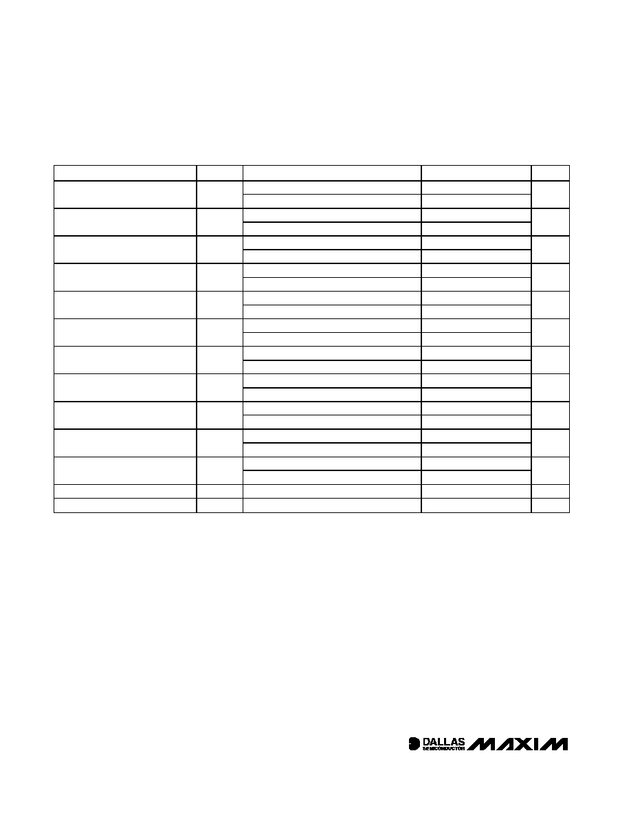
Ordering Information
Rev 1; 4/05
PART
RES0/RES1
RESISTANCE
(k
)
PIN-PACKAGE
DS1856E-050
50/50
16 TSSOP
DS1856E-050/T&R
50/50
16 TSSOP
DS1856B-050
50/50
16-Ball CSBGA
A
TOP VIEW
B
C
D
1
CSBGA (4mm x 4mm)
1.0mm PITCH
3
2
4
MON3
OUT1
IN2
MON1
L0
GND
N.C.
L1
H0
SDA
OUT2
H1
V
CC
SCL
IN1
MON2
16
15
14
13
12
11
10
9
1
2
3
4
5
6
7
8
SDA
V
CC
H1
L1
H0
L0
MON3
MON2
MON1
TSSOP
SCL
OUT1
IN2
IN1
OUT2
N.C.
GND
DS1856
Pin Configurations
DS1856
SDA
1
2
3
4
5
6
7
8
16
0.1
µF
15
14
13
12
11
10
9
SCL
OUT1
IN1
OUT2
IN2
N.C.
GND
V
CC
H1
L1
H0
L0
MON3
MON2
MON1
Rx POWER*
DIAGNOSTIC
INPUTS
TO LASER
MODULATION
CONTROL
TO LASER BIAS
CONTROL
DECOUPLING
CAPACITOR
Tx POWER*
Tx BIAS*
*SATISFIES SFF-8472 COMPATIBILITY
V
CC
V
CC
= 3.3V
4.7k
4.7k
Tx-FAULT
LOS
2-WIRE
INTERFACE
Typical Operating Circuit
Ordering Information continued at end of data sheet.
+Denotes lead free.
*Future product--contact factory for availability.
T&R denotes tape-and-reel.
All parts operate at the -40∞C to +95∞C temperature range.

DS1856
Dual, Temperature-Controlled Resistors with Inter-
nally Calibrated Monitors and Password Protection
2
_____________________________________________________________________
PARAMETER
SYMBOL
CONDITIONS
MIN
TYP
MAX
UNITS
Supply Voltage
V
CC
(Note 1)
2.85
5.50
V
Input Logic 1 (SDA, SCL)
V
IH
(Note 2)
0.7 x Vcc
V
CC
+ 0.3
V
Input Logic 0 (SDA, SCL)
V
IL
(Note 2)
-0.3
+0.3 x V
CC
V
Resistor Inputs (L0, L1, H0, H1)
-0.3
V
CC
+ 0.3
V
Resistor Current
I
RES
-3
+3
mA
High-Impedance Resistor Current
I
ROFF
0.001
0.1
µA
Input logic 1
1.6
Input Logic Levels (IN1, IN2)
Input logic 0
0.9
V
ABSOLUTE MAXIMUM RATINGS
Stresses beyond those listed under "Absolute Maximum Ratings" may cause permanent damage to the device. These are stress ratings only, and functional
operation of the device at these or any other conditions beyond those indicated in the operational sections of the specifications is not implied. Exposure to
absolute maximum rating conditions for extended periods may affect device reliability.
Voltage Range on V
CC
Relative to Ground ...........-0.5V to +6.0V
Voltage Range on Inputs Relative
to Ground* ..............................................-0.5V to (V
CC
+ 0.5V)
Voltage Range on Resistor Inputs Relative
to Ground* ..............................................-0.5V to (V
CC
+ 0.5V)
Current into Resistors............................................................5mA
Operating Temperature Range ...........................-40∞C to +95∞C
Programming Temperature Range .........................0∞C to +70∞C
Storage Temperature Range .............................-55∞C to +125∞C
Soldering Temperature .......................................See IPC/JEDEC
J-STD-020A
RECOMMENDED OPERATING CONDITIONS
(T
A
= -40∞C to +95∞C, unless otherwise noted.)
PARAMETER
SYMBOL
CONDITIONS
MIN
TYP
MAX
UNITS
Supply Current
I
CC
(Note 3)
1
2
mA
Input Leakage
I
IL
-200
+200
nA
V
OL1
3mA sink current
0
0.4
Low-Level Output Voltage
(SDA, OUT1, OUT2)
V
OL2
6mA sink current
0
0.6
V
Full-Scale Input (MON1, MON2,
MON3)
At factory setting
(Note 4)
2.4875
2.5
2.5125
V
Full-Scale V
CC
Monitor
At factory setting (Note 5)
6.5208
6.5536
6.5864
V
I/O Capacitance
C
I/O
10
pF
Digital Power-On Reset
POD
1.0
2.2
V
Analog Power-On Reset
POA
2.0
2.6
V
DC ELECTRICAL CHARACTERISTICS
(V
CC
= 2.85V to 5.5V, T
A
= -40∞C to +95∞C, unless otherwise noted.)
*Not to exceed 6.0V.

DS1856
Dual, Temperature-Controlled Resistors with Inter-
nally Calibrated Monitors and Password Protection
_____________________________________________________________________
3
PARAMETER
SYMBOL
CONDITIONS
MIN
TYP
MAX
UNITS
Thermometer Error
T
ERR
-40∞C to +95∞C
±3.0
∞C
DIGITAL THERMOMETER
(V
CC
= 2.85V to 5.5V, T
A
= -40∞C to +95∞C, unless otherwise noted.)
PARAMETER
SYMBOL
CONDITIONS
MIN
TYP
MAX
UNITS
EEPROM Writes
+70∞C (Note 14)
50,000
Writes
NONVOLATILE MEMORY CHARACTERISTICS
(V
CC
= 2.85V to 5.5V)
PARAMETER
SYMBOL
CONDITIONS
MIN
TYP
MAX
UNITS
Input Resolution
VMON
610
µV
Supply Resolution
V
CC
1.6
mV
Input/Supply Accuracy
(MON1, MON2, MON3, V
CC
)
A
CC
At factory setting
0.25
0.5
% FS
(full scale)
Update Rate for MON1, MON2,
MON3, Temp, or V
CC
t
frame
47
60
ms
Input/Supply Offset
(MON1, MON2, MON3, V
CC
)
V
OS
(Note 14)
0
5
LSB
ANALOG VOLTAGE MONITORING
(V
CC
= 2.85V to 5.5V, T
A
= -40∞C to +95∞C, unless otherwise noted.)
PARAMETER
CONDITIONS
MIN
TYP
MAX
UNITS
Position 00h Resistance (50k
)
T
A
= +25∞C
0.65
1.0
1.35
k
Position FFh Resistance (50k
)
T
A
= +25∞C
40
50
60
k
Position 00h Resistance (30k
)
T
A
= +25∞C
0.40
k
Position FFh Resistance (30k
)
T
A
= +25∞C
30
k
Position 00h Resistance (20k
)
T
A
= +25∞C
0.20
0.40
0.55
k
Position FFh Resistance (20k
)
T
A
= +25∞C
15
20
25
k
Position 00h Resistance (10k
)
T
A
= +25∞C
0.40
k
Position FFh Resistance (10k
)
T
A
= +25∞C
10
k
Position 00h Resistance (2.5k
)
T
A
= +25∞C
0.1
0.175
0.250
k
Position FFh Resistance (2.5k
)
T
A
= +25∞C
2.0
2.50
3.0
k
Absolute Linearity
(Note 6)
-2
+2
LSB
Relative Linearity
(Note 7)
-1
+1
LSB
Temperature Coefficient
(Note 8)
50
ppm/∞C
ANALOG RESISTOR CHARACTERISTICS
(V
CC
= 2.85V to 5.5V, T
A
= -40∞C to +95∞C, unless otherwise noted.)
DS1856
Dual, Temperature-Controlled Resistors with Inter-
nally Calibrated Monitors and Password Protection
4
_____________________________________________________________________
PARAMETER
SYMBOL
CONDITIONS
MIN
TYP
MAX
UNITS
Fast mode
0
400
SCL Clock Frequency (Note 9)
f
SCL
Standard mode
0
100
kHz
Fast mode
1.3
Bus Free Time Between STOP and
START Condition (Note 9)
t
BUF
Standard mode
4.7
µs
Fast mode
0.6
Hold Time (Repeated)
START Condition (Notes 9, 10)
t
HD:STA
Standard mode
4.0
µs
Fast mode
1.3
LOW Period of SCL Clock (Note 9)
t
LOW
Standard mode
4.7
µs
Fast mode
0.6
H IG H P er i od of S C L C l ock ( N ote 9)
t
HIGH
Standard mode
4.0
µs
Fast mode
0
0.9
Data Hold Time (Notes 9, 11, 12)
t
HD:DAT
Standard mode
0
µs
Fast mode
100
Data Setup Time (Note 9)
t
SU:DAT
Standard mode
250
ns
Fast mode
0.6
START Setup Time (Note 9)
t
SU:STA
Standard mode
4.7
µs
Fast mode
20 + 0.1C
B
300
Rise Time of Both SDA and SCL
Signals (Note 13)
t
R
Standard mode
20 + 0.1C
B
1000
ns
Fast mode
20 + 0.1C
B
300
Fall Time of Both SDA and SCL
Signals (Note 13)
t
F
Standard mode
20 + 0.1C
B
300
ns
Fast mode
0.6
Setup Time for STOP Condition
t
SU:STO
Standard mode
4.0
µs
Capacitive Load for Each Bus Line
C
B
(Note 13)
400
pF
EEPROM Write Time
t
W
10
20
ms
AC ELECTRICAL CHARACTERISTICS
(V
CC
= 2.85V to 5.5V, T
A
= -40∞C to +95∞C, unless otherwise noted. See Figure 6.)
Note 1:
All voltages are referenced to ground.
Note 2: I/O pins of fast-mode devices must not obstruct the SDA and SCL lines if V
CC
is switched off.
Note 3:
SDA and SCL are connected to V
CC
and all other input signals are connected to well-defined logic levels.
Note 4: Full scale is user programmable. The maximum voltage that the MON inputs read is approximately full scale, even if the volt-
age on the inputs is greater than full scale.
Note 5:
This voltage defines the maximum range of the analog-to-digital converter voltage, not the maximum V
CC
voltage.
Note 6: Absolute linearity is the difference of measured value from expected value at DAC position. The expected value is a
straight line from measured minimum position to measured maximum position.
Note 7: Relative linearity is the deviation of an LSB DAC setting change vs. the expected LSB change. The expected LSB change
is the slope of the straight line from measured minimum position to measured maximum position.
Note 8: See the Typical Operating Characteristics.
Note 9: A fast-mode device can be used in a standard-mode system, but the requirement t
SU:DAT
> 250ns must then be met. This
is automatically the case if the device does not stretch the LOW period of the SCL signal. If such a device does stretch the
LOW period of the SCL signal, it must output the next data bit to the SDA line t
RMAX
+ t
SU:DAT
= 1000ns + 250ns = 1250ns
before the SCL line is released.

DS1856
Dual, Temperature-Controlled Resistors with Inter-
nally Calibrated Monitors and Password Protection
_____________________________________________________________________
5
Note 10: After this period, the first clock pulse is generated.
Note 11: The maximum t
HD:DAT
only has to be met if the device does not stretch the LOW period (t
LOW
) of the SCL signal.
Note 12: A device must internally provide a hold time of at least 300ns for the SDA signal (see the V
IH MIN
of the SCL signal) to
bridge the undefined region of the falling edge of SCL.
Note 13: C
B
--total capacitance of one bus line, timing referenced to 0.9 x V
CC
and 0.1 x V
CC
.
Note 14: Guaranteed by design.
Typical Operating Characteristics
(V
CC
= 5.0V, T
A
= +25∞C, for both 50k
and 20k versions, unless otherwise noted.)
TEMPERATURE (
∞C)
40
60
80
20
0
-20
650
700
750
800
600
-40
100
SUPPLY CURRENT vs. TEMPERATURE
DS1856 toc01
SUPPLY CURRENT (
µ
A)
SDA = SCL = V
CC
SUPPLY CURRENT vs. VOLTAGE
DS1856 toc02
VOLTAGE (V)
SUPPLY CURRENT (
µ
A)
5.0
4.5
4.0
3.5
450
500
600
550
700
650
750
800
400
3.0
5.5
SDA = SCL = V
CC
RESISTANCE vs. SETTING
DS1856 toc03
SETTING (DEC)
RESISTANCE (k
)
200
150
100
50
10
20
30
40
50
60
0
0
250
50k
VERSION
RESISTANCE vs. SETTING
DS1856 toc04
SETTING (DEC)
RESISTANCE (k
)
200
150
100
50
5
10
15
20
0
0
250
20k
VERSION
ACTIVE SUPPLY CURRENT
vs. SCL FREQUENCY
DS1856 toc05
SCL FREQUENCY (kHz)
ACTIVE SUPPLY CURRENT (
µ
A)
300
200
100
720
740
760
780
800
700
0
400
SDA = V
CC
RESISTOR 0 INL (LSB)
DS1856 toc06
SETTING (DEC)
RESISTOR 0 INL (LSB)
225
200
150 175
50 75 100 125
25
-0.8
-0.6
-0.4
-0.2
0
0.2
0.4
0.6
0.8
1.0
-1.0
0
250