 | –≠–ª–µ–∫—Ç—Ä–æ–Ω–Ω—ã–π –∫–æ–º–ø–æ–Ω–µ–Ω—Ç: LM4051C | –°–∫–∞—á–∞—Ç—å:  PDF PDF  ZIP ZIP |

General Description
The LM4050/LM4051 are precision two-terminal, shunt-
mode, bandgap voltage references available in fixed
reverse breakdown voltages of 1.225V, 2.048V, 2.500V,
3.000V, 3.3V, 4.096V, and 5.000V. Ideal for space-criti-
cal applications, the LM4050/LM4051 are offered in the
subminiature 3-pin SC70 surface-mount packages
(1.8mm x 1.8mm), 50% smaller than comparable
devices in SOT23 surface-mount package (SOT23 ver-
sions are also available).
Laser-trimmed resistors ensure excellent initial
accuracy. With a 50ppm/∞C temperature coefficient,
these devices are offered in three grades of initial accu-
racy ranging from 0.1% to 0.5%. The LM4050/LM4051
have a 60µA to 15mA shunt-current capability with low
dynamic impedance, ensuring stable reverse break-
down voltage accuracy over a wide range of operating
temperatures and currents. The LM4050/LM4051 do
not require an external stabilizing capacitor while
ensuring stability with any capacitive loads.
The LM4050/LM4051 specifications are guaranteed
over the temperature range of -40∞C to +125∞C.
________________________Applications
Portable, Battery-Powered Equipment
Notebook Computers
Cell Phones
Industrial Process Controls
Features
o 50ppm/∞C (max) Temperature Coefficient
Guaranteed over the -40∞C to +125∞C
Temperature Range
o Ultra-Small 3-Pin SC70 Package
o 0.1% (max) Initial Accuracy
o Wide Operating Current Range: 60µA to 15mA
o Low 28µV
RMS
Output Noise (10Hz to 10kHz)
o 1.225V, 2.048V, 2.500V, 3.000V, 3.3V, 4.096V, and
5.000V Fixed Reverse Breakdown Voltages
o No Output Capacitors Required
o Tolerates Capacitive Loads
LM4050/LM4051
50ppm/∞C Precision Micropower Shunt Voltage
References with Multiple Reverse Breakdown Voltages
________________________________________________________________ Maxim Integrated Products
1
-
1
3
N.C.*
+
LM4050/
LM4051
SC70-3/SOT23-3
TOP VIEW
2
*PIN 3 MUST BE LEFT FLOATING
OR CONNECTED TO PIN 2.
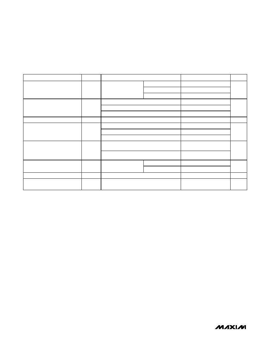
PART
TEMP RANGE
PIN-
PACKAGE
OUTPUT
VOLTAGE
(V)
LM4050_IM3-2.1
-40∞C to +125∞C
3 SOT23-3
2.048
LM4050_IX3-2.1
-40∞C to +125∞C
3 SC70-3
2.048
LM4050_IM3-2.5
-40∞C to +125∞C
3 SOT23-3
2.500
LM4050_IX3-2.5
-40∞C to +125∞C
3 SC70-3
2.500
LM4050_IM3-3.0
-40∞C to +125∞C
3 SOT23-3
3.000
LM4050_IX3-3.0
-40∞C to +125∞C
3 SC70-3
3.000
LM4050_EX3-3.3
-40∞C to +125∞C
3 SC70-3
3.300
LM4050_IM3-4.1
-40∞C to +125∞C
3 SOT23-3
4.096
LM4050_IX3-4.1
-40∞C to +125∞C
3 SC70-3
4.096
LM4050_IM3-5.0
-40∞C to +125∞C
3 SOT23-3
5.000
LM4050_IX3-5.0
-40∞C to +125∞C
3 SC70-3
5.000
LM4051_IM3-1.2
-40∞C to +125∞C
3 SOT23-3
1.225
LM4051_IX3-1.2
-40∞C to +125∞C
3 SC70-3
1.225
Pin Configuration
Typical Operating Circuit
Selector Guide
19-2563; Rev 1; 3/03
Ordering Information appears at end of data sheet.
For pricing, delivery, and ordering information, please contact Maxim/Dallas Direct! at
1-888-629-4642, or visit Maxim's website at www.maxim-ic.com.
LM4050/LM4051
I
LOAD
I
SHUNT
R
S
V
S
V
R
I
SHUNT
+ I
LOAD

LM4050/LM4051
50ppm/∞C Precision Micropower Shunt Voltage
References with Multiple Reverse Breakdown Voltages
2
_______________________________________________________________________________________
ABSOLUTE MAXIMUM RATINGS
ELECTRICAL CHARACTERISTICS--1.225V
(I
R
= 100µA, T
A
= T
MIN
to T
MAX
, unless otherwise noted. Typical values are at T
A
= +25∞C.) (Note 1)
Stresses beyond those listed under "Absolute Maximum Ratings" may cause permanent damage to the device. These are stress ratings only, and functional
operation of the device at these or any other conditions beyond those indicated in the operational sections of the specifications is not implied. Exposure to
absolute maximum rating conditions for extended periods may affect device reliability.
Reverse Current (cathode to anode) ..................................20mA
Forward Current (anode to cathode) ..................................10mA
ESD per Method 3015.7
Human Body Model .......................................................2000V
Machine Model.................................................................200V
Continuous Power Dissipation (T
A
= +70∞C)
3-Pin SC70 (derate 2.17mW/∞C above +70∞C) ............174mW
3-Pin SOT23 (derate 4.01mW/∞C above +70∞C)..........320mW
Operating Temperature Range
LM4050/LM4051_I_ _ _..................................-40∞C to +125∞C
Storage Temperature Range .............................-65∞C to +150∞C
Junction Temperature ......................................................+150∞C
Lead Temperature (soldering, 10s)..................................+300∞C
PARAMETER
SYMBOL
CONDITIONS
MIN
TYP
MAX
UNITS
LM4051A (0.1%)
1.2238
1.2250
1.2262
LM4051B (0.2%)
1.2226
1.2250
1.2275
Reverse Breakdown Voltage
V
R
T
A
= +25
∞C
LM4051C (0.5%)
1.2189
1.2250
1.2311
V
LM4051A
±1.2
±7
LM4051B
±2.4
±9
Reverse Breakdown Voltage
Tolerance (Note 2)
V
RTOL
LM4051C
±6.0
±12
mV
Minimum Operating Current
I
RMIN
45
60
µA
I
R
= 10mA
±20
I
R
= 1mA
±15
±50
Average Reverse Voltage
Temperature Coefficient
(Notes 2, 3)
V
R
/
T
I
R
= 100µA
±15
ppm/
∞C
I
RMIN
I
R
1mA
0.7
1.5
Reverse Breakdown Voltage
Change with Operating
Current Change
1mA
I
R
12mA
2.5
8.0
mV
Reverse Dynamic
Impedance (Note 3)
Z
R
I
R
= 1mA, f = 120Hz, I
AC
= 0.1I
R
0.5
1.5
Wideband Noise
e
N
I
R
= 100µA, 10Hz
f 10kHz
20
µV
RMS
Reverse Breakdown Voltage
Long-Term Stability
V
R
T = 1000h
120
ppm

LM4050/LM4051
50ppm/∞C Precision Micropower Shunt Voltage
References with Multiple Reverse Breakdown Voltages
_______________________________________________________________________________________
3
ELECTRICAL CHARACTERISTICS--2.048V
(I
R
= 100µA, T
A
= T
MIN
to T
MAX
, unless otherwise noted. Typical values are at T
A
= +25∞C.) (Note 1)
PARAMETER
SYMBOL
CONDITIONS
MIN
TYP
MAX
UNITS
LM4050A (0.1%)
2.0460
2.0480
2.0500
LM4050B (0.2%)
2.0439
2.0480
2.0521
Reverse Breakdown Voltage
V
R
T
A
= +25
∞C
LM4050C (0.5%)
2.0378
2.0480
2.0582
V
LM4050A
±2.0
±12
LM4050B
±4.0
±14
Reverse Breakdown Voltage
Tolerance (Note 2)
V
RTOL
LM4050C
±10
±20
mV
Minimum Operating Current
I
RMIN
45
65
µA
I
R
= 10mA
±20
I
R
= 1mA
±15
±50
Average Reverse Voltage
Temperature Coefficient
(Notes 2, 3)
V
R
/
T
I
R
= 100µA
±15
ppm/
∞C
I
RMIN
I
R
1mA
0.3
1.0
Reverse Breakdown Voltage
Change with Operating
Current Change
1mA
I
R
15mA
2.5
8.0
mV
LM4050A/B
0.3
0.8
Reverse Dynamic
Impedance (Note 3)
Z
R
I
R
= 1mA, f = 120Hz,
I
AC
= 0.1I
R
LM4050C
0.3
0.9
Wideband Noise
e
N
I
R
= 100µA, 10Hz
f 10kHz
28
µV
RMS
Reverse Breakdown Voltage
Long-Term Stability
V
R
T = 1000h
120
ppm
LM4050/LM4051
50ppm/∞C Precision Micropower Shunt Voltage
References with Multiple Reverse Breakdown Voltages
4
_______________________________________________________________________________________
ELECTRICAL CHARACTERISTICS--2.500V
(I
R
= 100µA, T
A
= T
MIN
to T
MAX
, unless otherwise noted. Typical values are at T
A
= +25∞C.) (Note 1)
PARAMETER
SYMBOL
CONDITIONS
MIN
TYP
MAX
UNITS
LM4050A (0.1%)
2.4975
2.5000
2.5025
LM4050B (0.2%)
2.4950
2.5000
2.5050
Reverse Breakdown Voltage
V
R
T
A
= +25
∞C
LM4050C (0.5%)
2.4875
2.5000
2.5125
V
LM4050A
±2.5
±15
LM4050B
±5.0
±18
Reverse Breakdown Voltage
Tolerance (Note 2)
V
RTOL
LM4050C
±13
±25
mV
Minimum Operating Current
I
RMIN
45
65
µA
I
R
= 10mA
±20
I
R
= 1mA
±15
±50
Average Reverse Voltage
Temperature Coefficient
(Notes 2, 3)
V
R
/
T
I
R
= 100µA
±15
ppm/
∞C
I
RMIN
I
R
1mA
0.3
1.0
Reverse Breakdown Voltage
Change with Operating
Current Change
1mA
I
R
15mA
2.5
8.0
mV
LM4050A/B
0.3
0.8
Reverse Dynamic
Impedance (Note 3)
Z
R
I
R
= 1mA, f = 120Hz,
I
AC
= 0.1I
R
LM4050C
0.3
0.9
Wideband Noise
e
N
I
R
= 100µA, 10Hz
f 10kHz
35
µV
RMS
Reverse Breakdown Voltage
Long-Term Stability
V
R
T = 1000h
120
ppm

LM4050/LM4051
50ppm/∞C Precision Micropower Shunt Voltage
References with Multiple Reverse Breakdown Voltages
_______________________________________________________________________________________
5
ELECTRICAL CHARACTERISTICS--3.000V
(I
R
= 100µA, T
A
= T
MIN
to T
MAX
, unless otherwise noted. Typical values are at T
A
= +25∞C.) (Note 1)
PARAMETER
SYMBOL
CONDITIONS
MIN
TYP
MAX
UNITS
LM4050A (0.1%)
2.9970
3.0000
3.0030
LM4050B (0.2%)
2.9940
3.0000
3.0060
Reverse Breakdown Voltage
V
R
T
A
= +25
∞C
LM4050C (0.5%)
2.9850
3.0000
3.0150
V
LM4050A
±3.0
±18
LM4050B
±6.0
±21
Reverse Breakdown Voltage
Tolerance (Note 2)
V
RTOL
LM4050C
±15
±30
mV
Minimum Operating Current
I
RMIN
45
67
µA
I
R
= 10mA
±20
I
R
= 1mA
±15
±50
Average Reverse Voltage
Temperature Coefficient
(Notes 2, 3)
V
R
/
T
I
R
= 100µA
±15
ppm/
∞C
I
RMIN
I
R
1mA
0.3
1.0
Reverse Breakdown Voltage
Change with Operating
Current Change
1mA
I
R
15mA
2.5
8.0
mV
LM4050A/B
0.3
0.8
Reverse Dynamic
Impedance (Note 3)
Z
R
I
R
= 1mA, f = 120Hz,
I
AC
= 0.1I
R
LM4050C
0.3
0.9
Wideband Noise
e
N
I
R
= 100µA, 10Hz
f 10kHz
45
µV
RMS
Reverse Breakdown Voltage
Long-Term Stability
V
R
T = 1000h
120
ppm
ELECTRICAL CHARACTERISTICS--3.300V
(I
R
= 100µA, T
A
= T
MIN
to T
MAX
, unless otherwise noted. Typical values are at T
A
= +25∞C.) (Note 1)
PARAMETER
SYMBOL
CONDITIONS
MIN
TYP
MAX
UNITS
LM4050A (0.1%)
3.2967
3.3000
3.3033
LM4050B (0.2%)
3.2934
3.3000
3.3066
Reverse Breakdown Voltage
V
R
T
A
= +25
∞C
LM4050C (0.5%)
3.2835
3.3000
3.3165
V
LM4050A
±3.0
±18
LM4050B
±6.0
±21
Reverse Breakdown Voltage
Tolerance (Note 2)
V
RTOL
LM4050C
±15
±30
mV
Minimum Operating Current
I
RMIN
45
67
µA
I
R
= 10mA
±20
I
R
= 1mA
±15
±50
Average Reverse Voltage
Temperature Coefficient
(Notes 2, 3)
V
R
/
T
I
R
= 100µA
±15
ppm/
∞C
I
RMIN
I
R
1mA
0.3
1.0
Reverse Breakdown Voltage
Change with Operating
Current Change
1mA
I
R
15mA
2.5
8.0
mV
LM4050A/B
0.3
0.8
Reverse Dynamic
Impedance (Note 3)
Z
R
I
R
= 1mA, f = 120Hz,
I
AC
= 0.1I
R
LM4050C
0.3
0.9
Wideband Noise
e
N
I
R
= 100µA, 10Hz
f 10kHz
50
µV
RMS
Reverse Breakdown Voltage
Long-Term Stability
V
R
T = 1000h
120
ppm