 | ÐлекÑÑоннÑй компоненÑ: MAX3235E | СкаÑаÑÑ:  PDF PDF  ZIP ZIP |
Äîêóìåíòàöèÿ è îïèñàíèÿ www.docs.chipfind.ru
For free samples & the latest literature: http://www.maxim-ic.com, or phone 1-800-998-8800.
For small orders, phone 1-800-835-8769.
________________General Description
The MAX3233E/MAX3235E are EIA/TIA-232 and V.28/V.24
communications interfaces with automatic shutdown/
wake-up features, high data-rate capabilities, and
enhanced electrostatic discharge (ESD) protection. All
transmitter outputs and receiver inputs are protected to
±15kV using IEC 1000-4-2 Air-Gap Discharge, to ±8kV
using IEC 1000-4-2 Contact Discharge, and to ±15kV
using the Human Body Model. The MAX3233E operates
from a +3.3V supply; the MAX3235E operates from +5.0V.
All devices achieve a 1µA supply current using Maxim's
revolutionary AutoShutdown PlusTM feature. These
devices automatically enter a low-power shutdown
mode when the following two conditions occur: either
the RS-232 cable is disconnected or the transmitters of
the connected peripherals are inactive, and the UART
driving the transmitter inputs is inactive for more than
30 seconds. They turn on again when they sense a
valid transition at any transmitter or receiver input.
AutoShutdown Plus saves power without changes to
the existing BIOS or operating system.
The MAX3233E/MAX3235E have internal dual charge
pumps requiring no external capacitors. Both trans-
ceivers have a proprietary low-dropout transmitter out-
put stage that enables true RS-232 performance from a
+3.0V to +3.6V supply for the MAX3233E or a +4.5V to
+5.5V supply for the MAX3235E. These devices are
guaranteed to operate up to 250kbps. Both are avail-
able in space-saving 20-pin wide SO or plastic DIP
packages.
________________________Applications
Subnotebook and Palmtop Computers
Cellular Phones
Battery-Powered Equipment
Hand-Held Equipment
Peripherals
Embedded Systems
____________________________Features
o
ESD Protection for RS-232 I/O Pins
±15kV--Human Body Model
±8kV--IEC 1000-4-2, Contact Discharge
±15kV--IEC 1000-4-2, Air-Gap Discharge
o
Latchup Free
o
1µA Supply Current
o
AutoShutdown Plus--1997 EDN Magazine
Innovation of the Year
o
Single-Supply Operation
+3.0V to +3.6V (MAX3233E)
+4.5V to +5.5V (MAX3235E)
o
250kbps Guaranteed Data Rate
o
6V/µs Guaranteed Slew Rate
o
Meets EIA/TIA-232 Specifications Down to 3.0V
(MAX3233E)
o
Internal Charge-Pump Capacitors
MAX3233E
/MAX3235E
±15kV ESD-Protected, 1µA, 250kbps, 3.3V/5V, Dual
RS-232 Transceivers with Internal Capacitors
________________________________________________________________
Maxim Integrated Products
1
19-1473; Rev 0; 4/99
PART
MAX3233E
CWP
0°C to +70°C
TEMP. RANGE
PIN-PACKAGE
20 SO
AutoShutdown Plus is a trademark of Maxim Integrated Products.
_______________Ordering Information
Ordering Information continued at end of data sheet.
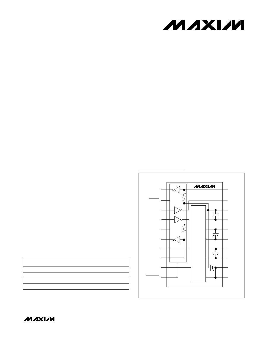
MAX3233E
MAX3235E
12
13
14
15
16
17
18
4
1
R2OUT
R2IN
T2OUT
GND
V-
C2-
C2+
C1-
C1+
V+
V+
INVALID
T2IN
T1IN
FORCEON
R1OUT
T1OUT
R1IN
V
CC
FORCEOFF
2
9
10
5
6
7
8
3
19
20
11
CHARGE
PUMP
SO/DIP
Pin Configuration/
Functional Diagram
Typical Operating Circuit appears at end of data sheet.
MAX3233ECPP
0°C to +70°C
20 Plastic DIP
MAX3233EEPP
-40°C to +85°C
20 Plastic DIP
MAX3233EEWP
-40°C to +85°C
20 SO
Covered by U.S. Patent numbers 4,636,930; 4,679,134; 4,777,577;
4,797,899; 4,809,152; 4,897,774; 4,999,761; 5,649,210; and other
patents pending.
MAX3233E
/MAX3235E
2
_______________________________________________________________________________________
ABSOLUTE MAXIMUM RATINGS
ELECTRICAL CHARACTERISTICS
(V
CC
= +3.0V to +3.6V for MAX3233E, V
CC
= +4.5V to +5.5V for MAX3235E; T
A
= T
MIN
to T
MAX
; unless otherwise noted. Typical val-
ues are at T
A
= +25°C.)
Stresses beyond those listed under "Absolute Maximum Ratings" may cause permanent damage to the device. These are stress ratings only, and functional
operation of the device at these or any other conditions beyond those indicated in the operational sections of the specifications is not implied. Exposure to
absolute maximum rating conditions for extended periods may affect device reliability.
V
CC
to GND (MAX3233E).........................................-0.3V to +4V
V
CC
to GND (MAX3235E).........................................-0.3V to +6V
V+ to GND (Note 1) ..................................................-0.3V to +7V
V- to GND (Note 1) ...................................................+0.3V to -7V
V+ +
|
V-
|
(Note 1).................................................................+13V
Input Voltages
T_IN, FORCEON, FORCEOFF to GND....................-0.3V to +6V
R_IN to GND ...................................................................±25V
Output Voltages
T_OUT to GND.............................................................±13.2V
R_OUT, INVALID to GND ......................-0.3V to (V
CC
+ 0.3V)
Short-Circuit Duration
T_OUT to GND ......................................................Continuous
Continuous Power Dissipation (T
A
= +70°C)
Wide SO (derate 10mW/°C above +70°C)..................800mW
Plastic DIP (derate 11.11mW/°C above +70°C) .........889mW
Operating Temperature Ranges
MAX323_EC_P ...................................................0°C to +70°C
MAX323_EE_P ................................................-40°C to +85°C
Storage Temperature Range .............................-65°C to +150°C
Lead Temperature (soldering, 10sec) .............................+300°C
Note 1:
V+ and V- can have maximum magnitudes of 7V, but their absolute difference cannot exceed 13V.
FORCEON = GND, FORCEOFF = V
CC
,
all R_IN idle, all T_IN idle
T
A
= +25°C
CONDITIONS
k
3
5
7
Input Resistance
V
0.5
Input Hysteresis
1.8
2.4
V
1.5
2.4
Input Threshold High
0.8
1.3
V
0.6
1.0
Input Threshold Low
V
-25
+25
Input Voltage Range
V
V
CC
- 0.6 V
CC
- 0.1
Output Voltage High
V
0.4
Output Voltage Low
µA
1
10
Supply Current, Shutdown
µA
1
10
Supply Current,
AutoShutdown Plus
µA
±0.01
±1
Transmitter Input Hysteresis
V
0.5
V
2.4
Input Logic Threshold High
mA
0.3
1
Supply Current,
AutoShutdown Plus Disabled
V
0.8
Input Logic Threshold Low
2
UNITS
MIN
TYP
MAX
SYMBOL
PARAMETER
FORCEOFF = GND
T
A
= +25°C
T_IN, FORCEON, FORCEOFF
FORCEON = FORCEOFF = V
CC
, no load
T_IN, FORCEON, FORCEOFF
I
OUT
= -1.0mA
I
OUT
= 1.6mA
Input Leakage Current
DC CHARACTERISTICS
(V
CC
= 3.3V for MAX3233E, V
CC
= 5.0V for MAX3235E, T
A
= +25°C
.
)
LOGIC INPUTS AND RECEIVER OUTPUTS
RECEIVER INPUTS
T
A
= +25°C
V
CC
= 5.0V, MAX3235E
V
CC
= 3.3V, MAX3233E
V
CC
= 5.0V, MAX3235E
V
CC
= 3.3V, MAX3233E
±15kV ESD-Protected, 1µA, 250kbps, 3.3V/5V, Dual
RS-232 Transceivers with Internal Capacitors
T_IN, FORCEON,
FORCEOFF
V
CC
= 5.0V, MAX3235E
V
CC
= 3.3V, MAX3233E
MAX3233E
/MAX3235E
_______________________________________________________________________________________
3
ELECTRICAL CHARACTERISTICS (continued)
(V
CC
= +3.0V to +3.6V for MAX3233E, V
CC
= +4.5V to +5.5V for MAX3235E; T
A
= T
MIN
to T
MAX
; unless otherwise noted. Typical val-
ues are at T
A
= +25°C.)
CONDITIONS
300
10M
Output Resistance
V
±5
±5.4
Output Voltage Swing
UNITS
MIN
TYP
MAX
SYMBOL
PARAMETER
Figure 3a
sec
15
30
60
t
AUTOSHDN
Receiver or Transmitter Edge to
Transmitters Shut Down
µs
100
t
WU
Receiver or Transmitter Edge to
Transmitters Enabled
µs
1
t
INVH
Receiver Positive or Negative
Threshold to INVALID High
V
V
CC
- 0.6
INVALID, Output Voltage High
V
0.4
INVALID Output Voltage Low
V
-0.3
0.3
Receiver Input Threshold to
INVALID Output Low
-2.7
V
2.7
Receiver Input Threshold to
INVALID Output High
±15
±8
R_IN, T_OUT
kV
±15
µA
±25
Output Leakage Current
±60
mA
Output Short-Circuit Current
V
CC
= V+ = V- = 0, transmitter outputs = ±2V
All transmitter outputs loaded with 3k
to
ground
Figure 3b (Note 2)
Figure 3b (Note 2)
Figure 3b
I
OUT
= -1.0mA
I
OUT
= -1.6mA
Figure 3a
Human Body Model
V
OUT
= ± 12V
transmitters
disabled
IEC1000-4-2 Contact Discharge
IEC1000-4-2 Air Discharge
V
CC
= 0 or +4.5V to
5.5V (MAX3235E)
V
CC
= 0 or +3.0V to
3.6V (MAX3233E)
±15kV ESD-Protected, 1µA, 250kbps, 3.3V/5V, Dual
RS-232 Transceivers with Internal Capacitors
±25
MAX3233E
MAX3235E
50
µs
70
t
INVL
Receiver Positive or Negative
Threshold to INVALID Low
Figure 3b
TRANSMITTER OUTPUTS
ESD PROTECTION
AutoShutdown PLUS
(FORCEON = GND, FORCEOFF = V
CC
)
Positive threshold
Negative threshold
ns
MAX3233E
/MAX3235E
4
_______________________________________________________________________________________
TIMING CHARACTERISTICS (continued)
(V
CC
= +3.0V to +3.6V for MAX3233E, V
CC
= +4.5V to +5.5V for MAX3235E; T
A
= T
MIN
to T
MAX
; unless otherwise noted. Typical val-
ues are at T
A
= +25°C.)
Note 2:
A transmitter/receiver edge is defined as a transition through the transmitter/receiver input logic thresholds.
Note 3:
Transmitter skew is measured at the transmitter zero cross points.
C
L
= 150pF
to 2500pF
C
L
= 150pF
to 1000pF
R_IN to R_OUT,
C
L
= 150pF
R
L
= 3k
, C
L
= 1000pF,
one transmitter switching
V
CC
= 3.3V (MAX3233E),
V
CC
= 5.0V (MAX3235E),
T
A
= +25°C,
R
L
= 3k
to 7k
,
measured from +3V to -3V
or -3V to +3V
Normal operation
Normal operation
(Note 3)
CONDITIONS
100
ns
70
t
PHL
kbps
250
Maximum Data Rate
Receiver Propagation Delay
V/µs
4
30
6
30
Transition-Region Slew Rate
ns
200
Receiver Output Enable Time
ns
200
Receiver Output Disable Time
ns
150
t
PHL
- t
PLH
Transmitter Skew
ns
180
t
PHL
- t
PLH
Receiver Skew
UNITS
MIN
TYP
MAX
SYMBOL
PARAMETER
-10.0
-7.5
V
OUT
-
V
OUT
+
-5.0
-2.5
0
2.5
5.0
7.5
10.0
0
1000
2000
3000
4000
5000
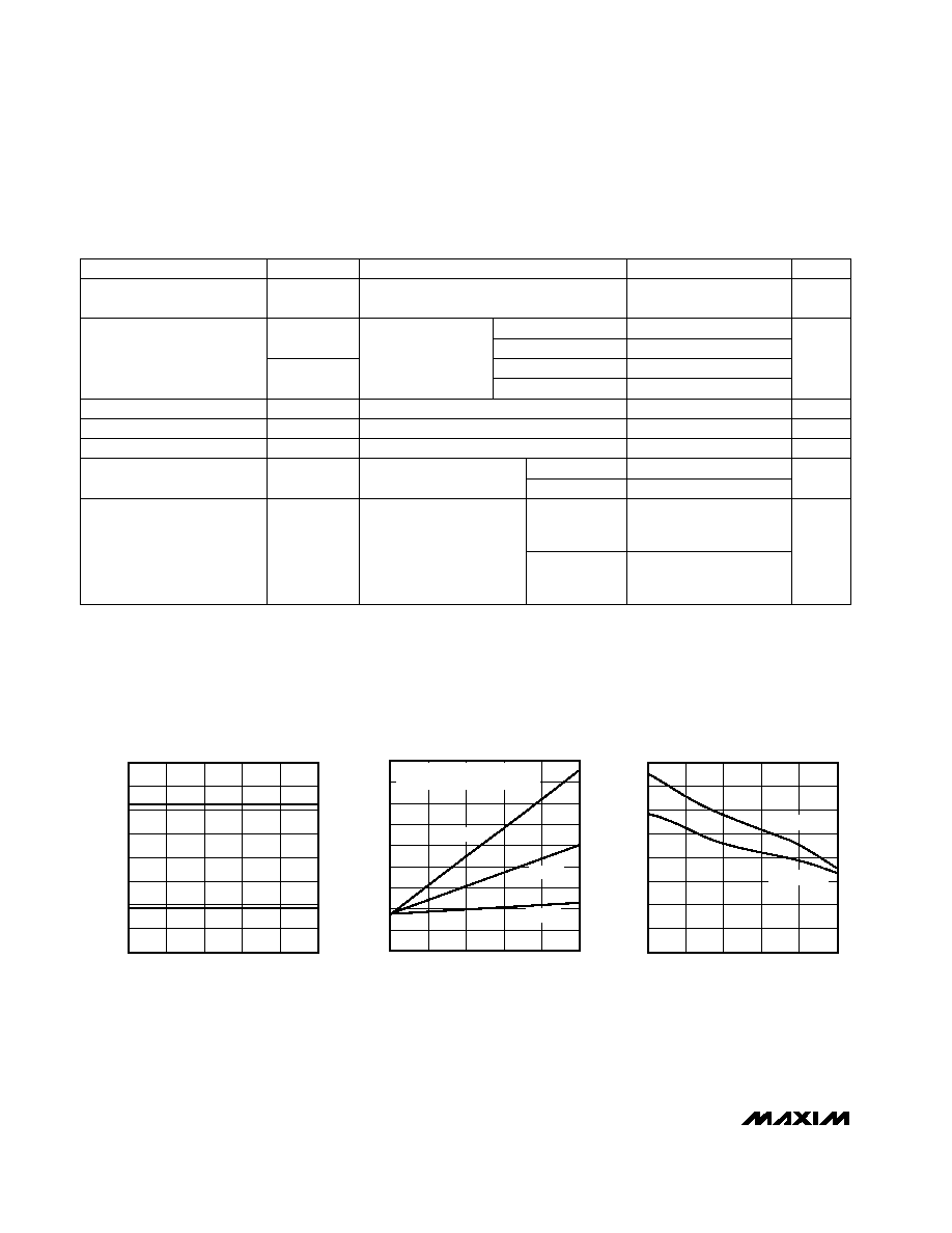
TRANSMITTER OUTPUT VOLTAGE vs.
LOAD CAPACITANCE
MAX3233E/35Etoc01
LOAD CAPACITANCE (pF)
TRANSMITTER OUTPUT VOLTAGE (V)
0
10
5
25
20
15
40
35
30
45
0
2000
1000
3000
4000
5000
OPERATING SUPPLY CURRENT
vs. LOAD CAPACITANCE
MAX3233E/35E toc02
LOAD CAPACITANCE (pF)
SUPPLY CURRENT (mA)
TRANSMITTER 1 AT DATA RATE
TRANSMITTER 2 AT 1/16 DATA RATE
20kbps
120kbps
250kbps
0
2
4
6
8
10
12
14
16
0
1000
2000
3000
4000
5000
SLEW RATE vs.
LOAD CAPACITANCE
MAX3233E/35Etoc01
LOAD CAPACITANCE (pF)
SLEW RATE (V/
µ
s)
SLEW RATE -
SLEW RATE +
__________________________________________Typical Operating Characteristics
(V
CC
= +3.3V for MAX3233E, V
CC
= +5.0V for MAX3235E; 250kbps data rate; all transmitters loaded with 3k
and C
L
; T
A
= +25°C;
unless otherwise noted.)
±15kV ESD-Protected, 1µA, 250kbps, 3.3V/5V, Dual
RS-232 Transceivers with Internal Capacitors
150
250
t
PLH
MAX3233E
MAX3235E
MAX3233E
MAX3235E
50
MAX3235E
MAX3233E
MAX3233E
/MAX3235E
_______________________________________________________________________________________
5
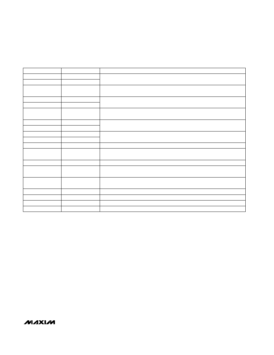
______________________________________________________________Pin Description
TTL/CMOS Receiver Outputs
FUNCTION
PIN
NAME
1
3
7
8
9
10
11, 12
14
15
R2OUT
16
17
18
Invalid Signal Detector Output, active low. A logic high indicates that a valid RS-232
level is present on a receiver.
T2N
TTL/CMOS Transmitter Outputs
2
INVALID
5
T1OUT
RS-232 Transmitter Outputs
FORCEON
Force-On Input, active high. Drive high to override AutoShutdown Plus, keeping
transmitters and receivers active (FORCEOFF must be high) (Table 1).
13
R1IN
RS-232 Receiver Outputs
C1+
Positive terminal of the internal voltage-doubling charge-pump capacitor. Leave
unconnected or connect to an external 0.1µF capacitor. See
Charge Pump Section.
V
CC
Supply Voltage (MAX3233E = +3.3V, MAX3235E = +5.0V)
FORCEOFF
Force-Off Input, active low. Drive low to shut down transmitters, receivers, and charge
pump. This overrides AutoShutdown Plus and FORCEON (Table 1).
V+
+5.5V generated by the charge pump. Do not connect.
C1-
Negative terminal of the internal voltage-doubling charge-pump capacitor. Leave
unconnected or connect to an external 0.1µF capacitor. See
Charge Pump Section.
C2+
Positive terminal of the internal inverting charge-pump capacitor. Do not connect.
C2-
Negative terminal of the internal inverting charge-pump capacitor. Do not connect.
V-
-5.5V generated by the charge pump. Do not connect.
GND
Ground
±15kV ESD-Protected, 1µA, 250kbps, 3.3V/5V, Dual
RS-232 Transceivers with Internal Capacitors
6
R1OUT
4
T1IN
19
T2OUT
20
R2IN