 | –≠–ª–µ–∫—Ç—Ä–æ–Ω–Ω—ã–π –∫–æ–º–ø–æ–Ω–µ–Ω—Ç: MAX338 | –°–∫–∞—á–∞—Ç—å:  PDF PDF  ZIP ZIP |
________________General Description
The MAX3385E is a 3V-powered EIA/TIA-232 and
V.28/V.24 communications interface with low power
requirements, high data-rate capabilities, and en-
hanced electrostatic discharge (ESD) protection. All
transmitter outputs and receiver inputs are protected to
±15kV using IEC 1000-4-2 Air-Gap Discharge, ±8kV
using IEC 1000-4-2 Contact Discharge, and ±15kV
using the Human Body Model.
The transceiver has a proprietary low-dropout transmit-
ter output stage, delivering true RS-232 performance
from a +3.0V to +5.5V supply with a dual charge pump.
The charge pump requires only four small 0.1µF capac-
itors for operation from a +3.3V supply. Each device is
guaranteed to run at data rates of 250kbps while main-
taining RS-232 output levels.
The MAX3385E has two receivers and two drivers. It
features a 1µA shutdown mode that reduces power con-
sumption and extends battery life in portable systems.
Its receivers can remain active in shutdown mode,
allowing external devices such as modems to be moni-
tored using only 1µA supply current.
The MAX3385E is available in a space-saving SSOP
package in either the commercial (0∞C to +70∞C) or
extended-industrial (-40∞C to +85∞C) temperature range.
________________________Applications
Hand-Held Equipment
Battery-Powered
Peripherals
Equipment
Printers
____________________________Features
o ESD Protection for RS-232 I/O Pins
±15kV--Human Body Model
±8kV--IEC 1000-4-2, Contact Discharge
±15kV--IEC 1000-4-2, Air-Gap Discharge
o Latchup Free
o 300µA Supply Current
o 1µA Low-Power Shutdown with Receivers Active
o 250kbps Guaranteed Data Rate
o 250µs Time to Exit Shutdown with 3k Load on V+
o 6V/µs Guaranteed Slew Rate
o Meets EIA/TIA-232 Specifications Down to 3.0V
MAX3385E
±15kV ESD-Protected, 3.0V to 5.5V, Low-Power,
up to 250kbps, True RS-232 Transceiver
________________________________________________________________ Maxim Integrated Products
1
20
19
18
17
16
15
14
13
1
2
3
8
12
11
10
4
5
6
7
SHDN
V
CC
GND
T1OUT
C1-
V+
C1+
N.C.
R1IN
R1OUT
T2IN
R2OUT
T2OUT
V-
C2-
C2+
9
R2IN
N.C.
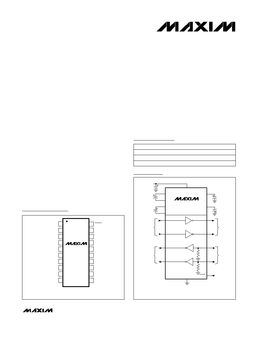
SSOP
T1IN
N.C.
MAX3385E
TOP VIEW
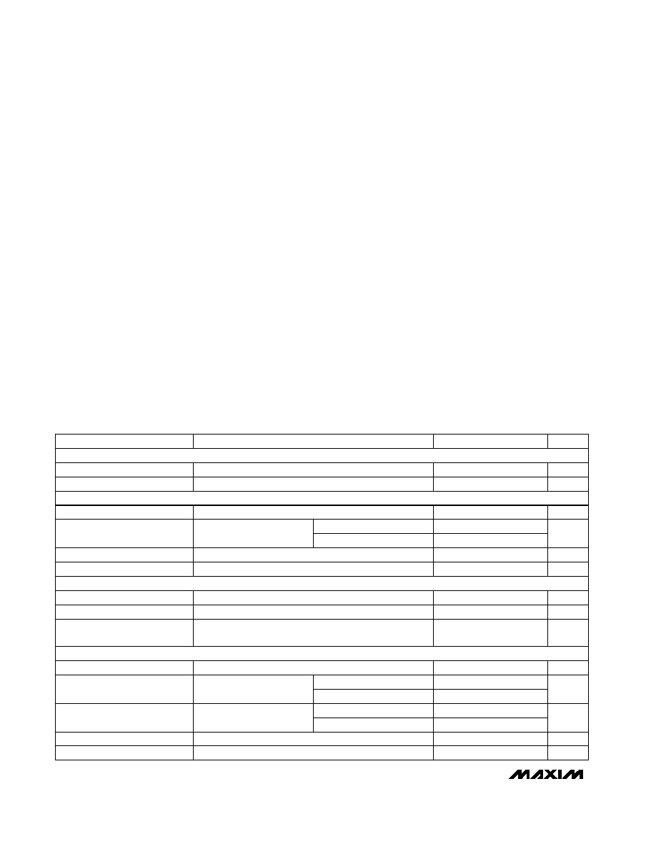
MAX3385E
R2OUT
R1OUT
R2IN
GND
RS-232
OUTPUTS
TTL/CMOS
INPUTS
T2IN
T1IN
C2-
C2+
C1-
C1+
R1IN
T2OUT
T1OUT
V-
V+
V
CC
C1
0.1
µF
C2
0.1
µF
C
BYPASS
+3.3V
RS-232
INPUTS
TTL/CMOS
OUTPUTS
5k
5k
SHDN
C3
*
0.1
µF
C4
0.1
µF
*
C3 CAN BE RETURNED TO EITHER V
CC
OR GROUND.
NOTE: SEE TABLE 2 FOR CAPACITOR SELECTION
Pin Configurations
19-1437; Rev 1; 10/99
Covered by U.S. Patent numbers 4,636,930; 4,679,134; 4,777,577; 4,797,899; 4,809,152; 4,897,774; 4,999,761; and other patents pending.
Typical Operating Circuit
Ordering Information
PART
MAX3385ECAP
MAX3385EEAP
-40∞C to +85∞C
0∞C to +70∞C
TEMP. RANGE
PIN-PACKAGE
20 SSOP
20 SSOP
For free samples & the latest literature: http://www.maxim-ic.com, or phone 1-800-998-8800.
For small orders, phone 1-800-835-8769.
MAX3385ECWN
0∞C to +70∞C
18 SO
Pin Configurations continued at end of data sheet.
MAX3385E
±15kV ESD-Protected, 3.0V to 5.5V, Low-Power,
up to 250kbps, True RS-232 Transceiver
2
_______________________________________________________________________________________
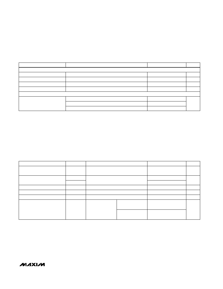
ABSOLUTE MAXIMUM RATINGS
ELECTRICAL CHARACTERISTICS
(V
CC
= +3V to +5.5V, C1≠C4 = 0.1µF, tested at 3.3V ±10%; C1 = 0.047µF, C2≠C4 = 0.33µF, tested at 5.0V ±10%; T
A
= T
MIN
to T
MAX
,
unless otherwise noted. Typical values are at T
A
= +25∞C.)
Stresses beyond those listed under "Absolute Maximum Ratings" may cause permanent damage to the device. These are stress ratings only, and functional
operation of the device at these or any other conditions beyond those indicated in the operational sections of the specifications is not implied. Exposure to
absolute maximum rating conditions for extended periods may affect device reliability.
V
CC
to GND ..............................................................-0.3V to +6V
V+ to GND (Note 1) ..................................................-0.3V to +7V
V- to GND (Note 1) ...................................................+0.3V to -7V
V+ + |V-| (Note 1) .................................................................+13V
Input Voltages
T_IN, SHDN to GND ..............................................-0.3V to +6V
R_IN to GND .....................................................................±25V
Output Voltages
T_OUT to GND...............................................................±13.2V
R_OUT .....................................................-0.3V to (V
CC
+ 0.3V)
Short-Circuit Duration, T_OUT to GND.......................Continuous
Continuous Power Dissipation (T
A
= +70∞C)
20-Pin SSOP (derate 8.00mW/∞C above +70∞C) ..........640mW
18-Pin SO (derate 9.52mW/∞C above +70∞C)...............762mW
Operating Temperature Ranges
MAX3385ECAP ....................................................0∞C to +70∞C
MAX3385ECWN ...................................................0∞C to +70∞C
MAX3385EEAP .................................................-40∞C to +85∞C
Storage Temperature Range .............................-65∞C to +150∞C
Lead Temperature (soldering, 10sec) .............................+300∞C
T
A
= +25∞C
SHDN = V
CC
, no load
T
A
= +25∞C
T
A
= +25∞C
I
OUT
= 1.6mA
R_OUT, receivers disabled
T_IN, SHDN
T_IN, SHDN
I
OUT
= -1.0mA
CONDITIONS
k
3
5
7
Input Resistance
V
0.5
Input Hysteresis
V
1.8
2.4
Input Threshold High
1.5
2.4
V
0.8
1.5
Input Threshold Low
0.6
1.2
V
-25
+25
Input Voltage Range
V
V
CC
-
V
CC
-
0.6
0.1
Output Voltage High
mA
0.3
1
Supply Current
V
0.4
Output Voltage Low
µA
±0.05
±10
Output Leakage Current
V
0.5
Transmitter Input Hysteresis
V
0.8
Input Logic Threshold Low
2.0
V
2.4
Input Logic Threshold High
UNITS
MIN
TYP
MAX
PARAMETER
Note 1: V+ and V- can have maximum magnitudes of 7V, but their absolute difference cannot exceed 13V.
V
CC
= 5.0V
V
CC
= 3.3V
V
CC
= 3.3V
V
CC
= 5.0V
V
CC
= 3.3V
V
CC
= 5.0V
T_IN, SHDN
µA
±0.01
±1
Input Leakage Current
SHDN = GND
µA
1
10
Shutdown Supply Current
DC CHARACTERISTICS (V
CC
= +3.3V or +5V, T
A
= +25∞C)
LOGIC INPUTS
RECEIVER OUTPUTS
RECEIVER INPUTS
MAX3385E
±15kV ESD-Protected, 3.0V to 5.5V, Low-Power,
up to 250kbps, True RS-232 Transceiver
_______________________________________________________________________________________
3
Note 2: Transmitter skew is measured at the transmitter zero cross points.
ELECTRICAL CHARACTERISTICS (continued)
(V
CC
= +3V to +5.5V, C1≠C4 = 0.1µF, tested at 3.3V ±10%; C1 = 0.047µF, C2≠C4 = 0.33µF, tested at 5.0V ±10%; T
A
= T
MIN
to T
MAX
,
unless otherwise noted. Typical values are at T
A
= +25∞C.)
Receiver input to receiver output,
C
L
= 150pF
R
L
= 3k
, C
L
= 1000pF,
one transmitter switching
V
CC
= 3.3V,
T
A
= +25∞C,
R
L
= 3k
to 7k,
measured from +3V
to -3V or -3V to +3V
V
OUT
+3.7V, R
LOAD
at V+ = 3k
(Note 2)
CONDITIONS
µs
0.15
t
PLH
Receiver Propagation Delay
0.15
t
PHL
kbps
250
Maximum Data Rate
6
30
µs
250
Time to Exit Shutdown
ns
100
t
PHL
- t
PLH
Transmitter Skew
ns
50
t
PHL
- t
PLH
Receiver Skew
UNITS
MIN
TYP
MAX
SYMBOL
PARAMETER
V
CC
= V+ = V- = 0, transmitter output = ±2V
All transmitter outputs loaded with 3k
to ground
IEC1000-4-2 Contact Discharge
IEC1000-4-2 Air Discharge
Human Body Model
V
CC
= 0 or 3V to 5.5V, V
OUT
= ±12V, transmitters disabled
CONDITIONS
300
10M
Output Resistance
V
±5
±5.4
Output Voltage Swing
±8
R_IN, T_OUT
±15
kV
±15
mA
±60
Output Short-Circuit Current
µA
±25
Output Leakage Current
UNITS
MIN
TYP
MAX
PARAMETER
TIMING CHARACTERISTICS
(V
CC
= +3V to +5.5V, C1≠C4 = 0.1µF, tested at 3.3V ±10%; C1 = 0.047µF, C2≠C4 = 0.33µF, tested at 5.0V ±10%; T
A
= T
MIN
to T
MAX
,
unless otherwise noted. Typical values are at T
A
= +25∞C.)
C
L
= 150pF to
1000pF
C
L
= 150pF to
2500pF
V/µs
4
30
Transition-Region Slew Rate
TRANSMITTER OUTPUTS
ESD PROTECTION

PIN
MAX3385E
±15kV ESD-Protected, 3.0V to 5.5V, Low-Power,
up to 250kbps, True RS-232 Transceiver
4
_______________________________________________________________________________________
__________________________________________Typical Operating Characteristics
(V
CC
= +3.3V, 250kbps data rate, 0.1µF capacitors, all transmitters loaded with 3k
and C
L
, T
A
= +25∞C, unless otherwise noted.)
-6
-5
-4
-3
-2
-1
0
1
2
3
4
5
6
0
1000
2000
3000
4000
5000
TRANSMITTER OUTPUT VOLTAGE
vs. LOAD CAPACITANCE
MAX3385E-01
LOAD CAPACITANCE (pF)
TRANSMITTER OUTPUT VOLTAGE (V)
T1 TRANSMITTING AT 250kbps
T2 TRANSMITTING AT 15.6kbps
V
OUT+
V
OUT-
0
6
2
4
10
8
14
12
16
0
1000
2000
3000
4000
5000
SLEW RATE vs. LOAD CAPACITANCE
MAX3885E-02
LOAD CAPACITANCE (pF)
SLEW RATE (V/
µ
s)
+SLEW
FOR DATA RATES UP TO 250kbps
-SLEW
0
25
20
15
5
10
35
30
40
45
0
2000
1000
3000
4000
5000
OPERATING SUPPLY CURRENT
vs. LOAD CAPACITANCE
MAX3885E-03
LOAD CAPACITANCE (pF)
SUPPLY CURRENT (mA)
250kbps
120kbps
20kbps
T1 TRANSMITTING AT 250kbps
T2 TRANSMITTING AT 15.6kbps
1
No Connection. Not internally connected.
N.C.
3
+5.5V generated by the charge pump.
V+
4
Negative terminal of the voltage-doubler charge-pump capacitor.
C1-
5
Positive terminal of inverting charge-pump capacitor.
C2+
6
Negative terminal of inverting charge-pump capacitor.
C2-
7
-5.5V generated by the charge pump.
V-
8, 15
RS-232 Transmitter Outputs
T_OUT
9, 14
RS-232 Receiver Inputs
R_IN
10, 13
TTL/CMOS Receiver Outputs
R_OUT
11, 12
TTL/CMOS Transmitter Inputs
T_IN
16
Ground
GND
17
+3.0V to +5.5V Supply Voltage
V
CC
18
Active-Low Shutdown-Control Input. Drive low to shut down transmitters and charge
SHDN
FUNCTION
NAME
______________________________________________________________ Pin Description
2
Positive terminal of the voltage-doubler charge-pump capacitor.
C1+
PIN
2
1, 10, 11
3
4
5
6
7
8, 17
9, 16
12, 15
13, 14
18
19
20
SO
SSOP

MAX3385E
±15kV ESD-Protected, 3.0V to 5.5V, Low-Power,
up to 250kbps, True RS-232 Transceiver
_______________________________________________________________________________________
5
_______________Detailed Description
Dual Charge-Pump Voltage Converter
The MAX3385E's internal power supply consists of a
regulated dual charge pump that provides output volt-
ages of +5.5V (doubling charge pump) and -5.5V
(inverting charge pump), over the 3.0V to 5.5V V
CC
range. The charge pump operates in discontinuous
mode; if the output voltages are less than 5.5V, the
charge pump is enabled, and if the output voltages
exceed 5.5V, the charge pump is disabled. Each
charge pump requires a flying capacitor (C1, C2) and a
reservoir capacitor (C3, C4) to generate the V+ and V-
supplies (Figure 1).
RS-232 Transmitters
The transmitters are inverting level translators that con-
vert CMOS-logic levels to ±5.0V EIA/TIA-232 levels.
The MAX3385E transmitters guarantee a 250kbps data
rate with worst-case loads of 3k
in parallel with 1000pF,
providing compatibility with PC-to-PC communication
software (such as LapLinkTM). Transmitters can be paral-
leled to drive multiple receivers or mice.
The MAX3385E's transmitters are disabled and the out-
puts are forced into a high-impedance state when the
device is in shutdown (SHDN = GND). The MAX3385E
permits the outputs to be driven up to ±12V in shut-
down.
The transmitter inputs do not have pull-up resistors.
Connect unused inputs to GND or V
CC
.
RS-232 Receivers
The receivers convert RS-232 signals to CMOS-logic
output levels (Table 1).
Shutdown Mode
Supply current falls to less than 1µA in shutdown mode
(SHDN = low). When shut down, the device's charge
pumps are shut off, V+ is pulled down to V
CC
, V- is
pulled to ground, and the transmitter outputs are dis-
abled (high impedance). The time required to exit shut-
0
SHDN
1
High-Z
T_OUT
Active
Active
R_OUT
Active
MAX3385E
5k
R_ IN
R_ OUT
C2-
C2+
C1-
C1+
V-
V+
V
CC
C4
C1
C2
0.1
µF
V
CC
SHDN
T_ OUT
T_ IN
GND
V
CC
7k
150pF
MAX3385E
5k
R_ IN
R_ OUT
C2-
C2+
C1-
C1+
V-
V+
V
CC
C4
C3
3k
C3
3k
C1
C2
0.1
µF
V
CC
SHDN
T_ OUT
T_ IN
GND
V
CC
3k
2500pF
MINIMUM SLEW-RATE TEST CIRCUIT
MAXIMUM SLEW-RATE TEST CIRCUIT
Figure 1. Slew-Rate Test Circuits
Table 1. Shutdown Truth Table
Laplink is a trademark of Traveling Software.