MBR12020
THRU
MBR120100
120 Amp
Rectifier
20 to 100 Volts
Features
∑
Operating
Junction Temperature: -55
∞
C to +1
75
∞
C
∑
Storage Temperature: -
55
∞
C to +1
75
∞
C
MCC
Part Number
Maximum
Recurrent
Peak Reverse
Voltage
Maximum
RMS Voltage
Maximum DC
Blocking
Voltage
MBR12020
20V 14V 20V
MBR12030
30V 21V 30V
MBR12035
35V 24.5V 35V
MBR12040
40V 28V 40V
MBR12045
45V 31.5V 45V
MBR12060
60V 42V 60V
MBR12080
80V 56V 80V
Electrical Characteristics @ 25
∞
C Unless Otherwise Specified
Average Forward
Current
I
F(AV)
12
0 A T
C
=
136∞
C
Peak Forward Surge
Current
I
FSM
20
00A 8.3ms, half sine
Maximum DC
Reverse Current At
Rated DC Blocking
Voltage
I
R
4
mA T
J
= 25
∞
C
Typical Junction
Capacitance
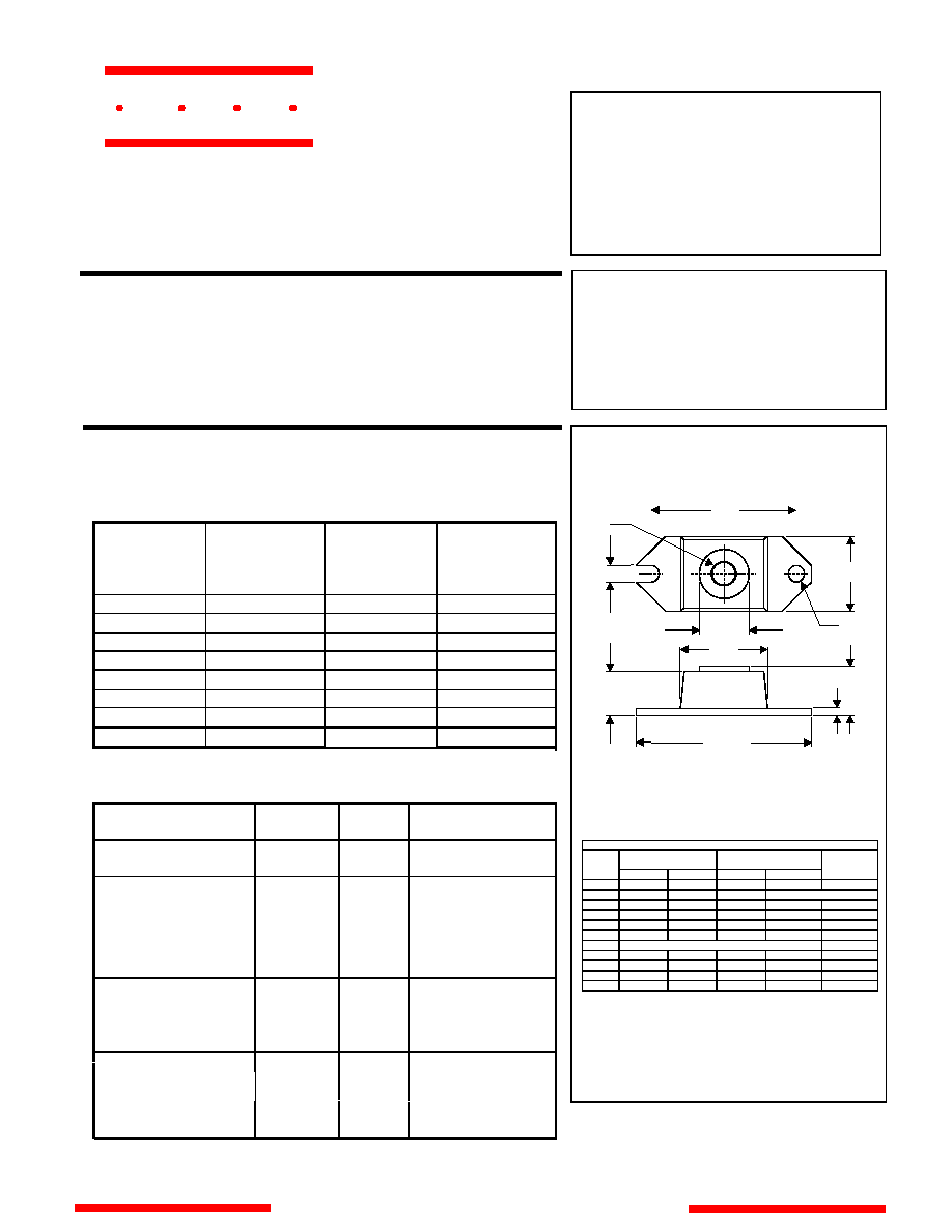
DIMENSIONS
M C C
www.
mccsemi
.com
Schottky Barrier
Maximum Ratings
∑
Metal of siliconrectifier, majonty carrier conducton
∑
Guard ring for transient protection
∑
Low power loss high efficiency
∑
High surge capacity, High current capability
MBR12
020-12045
MBR12
060
MBR12
080-120100
.63 V
.84 V
MBR120100
100V 70V 100V
HALF PACK
D
J
G
B
F
K
E
H
L
C
A
*Pulse Test: Pulse Width 300
µ
sec, Duty Cycle
2%
.75 V
Maximum
Instantaneous
Forward Voltage
I
FM
=
120.0A;
T
J
= 25
∞
C
V
F
75
mA
T
J
=
125
∞
C
MBR12020-12045
MBR12060
MBR12080-120100
C
J
4600pF Measured at
1.0MHz, V
R
=
5.0V
4300pF
3000pF
INCHES
MM
B .725 .775 18.42 19.69
A 1.515 1.560 38.48 39.62
C
.595 .625 15.11 15.88
E .
745 .755 18.92 19.18
F
.152 .160 3.8 6 4.06
G 1/4 - 20 UNC - 2B
H .
540 .580 13.72 14.73
J
.15 .160 3.96 4.06
K .
495 .505 12.57 12.83
L .120 .130 3.05 3.30
D 1.182 1.192 30.02 30.28
MIN
MAX
MIN
MAX
DIM
NOTE
omponents
21201 Itasca Street Chatsworth
!"#
$
% !"#
∑
Typical Thermal Resistance
per leg
0.
8∞
C/W Junction to Case
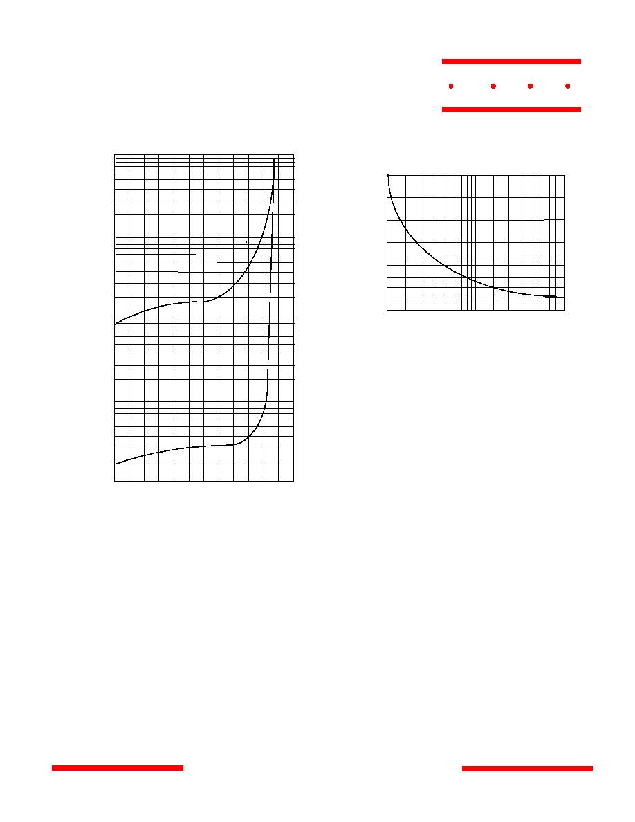
Junction Capacitance - pF versus
Reverse Voltage - Volts
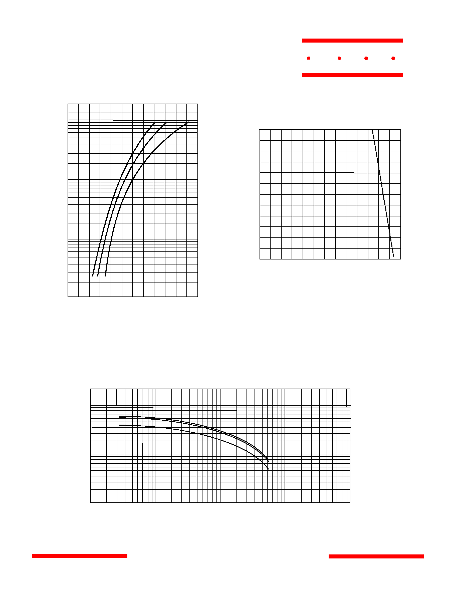
Instantaneous Forward Current - Amperes versus
Instantaneous Forward Voltage - Volts
Figure 1
Typical Forward Characteristics
4
00
6
00
20
00
10
00
Amps
0.
2 0.4 0.6 0.8 1.0 1.2
1
2
4
6
1
0
2
0
4
0
6
0
1
00
2
00
25
∞
C
Volts
Figure 3
Junction Capacitance
.1
.2
1
.4
2
10
20
40
4
100 200
1
00
2
00
6
00
1
000
2
000
1000
0
pF
Volts
60
00
4
000
4
00
400
1000
T
J
=25
∞
C
MBR120
20 thru MBR120100
www.
mccsemi
.com
M C C
Average Forward Rectified Current - Amperes versus
Ambient Temperature -
∞
C
Figure 2
Forward Derating Curve
0 150
50 7
0 90 110
0
20
40
60
Single Phase, Half Wave
60Hz Resistive or Inductive Load
Amps
∞
C
1
30
80
100
120
MBR12020-12045
MBR12060
MBR12080-120100
MBR12020-12045
MBR12060
MBR12080-120100
MBR120
20 thru MBR120100
www.
mccsemi
.com
M C C
Instantaneous Reverse Leakage Current - MicroAmperes versus
Percent Of Rated Peak Reverse Voltage - Volts
Figure 4
Typical Reverse Characteristics
Volts
40
60
200
100
mAmps
0 20 40 60 80 100
.1
.2
.4
.6
1.0
2
.0
4.0
6.0
10
20
T
J
=25
∞
C
400
600
1000
120
T
J
=
125
∞
C
1
100
4
0
200
400
8
00
8
Figure
5
Peak Forward Surge Current
Peak Forward Surge Current - Amperes versus
Number Of Cycles At 60Hz - Cycles
Amps
Cycles
2
6
10 20
60 80
40
1200
16
00
2000