Features
l
Economical series
l
Available in both unidirectional and bidirectional construction
l
6.8 to 440 stand-off volts available
l
600 watts peak pulse power dissipation
Mechanical Characteristics
l
CASE: Void free transfer molded thermosetting plastic
l
FINISH: Silver plated copper readily solderable.
l
POLARITY: Banded denotes cathode. Bidirectional not marked.
l
WEIGHT: 0.7 Gram(Appx.).
l
MOUNTING POSITION: Any.
Maximum Ratings
Peak Pulse Power Dissipation at 25
o
C: 600Watts
Steady State Power Dissipatoin:5 Watts at T
L
=+75
o
C
3/8" Lead Length
t
clamping
(0 Volts to BV Min.):
Unidirectional<1x10
-12
Seconds; Bidirectoinal<5x10
-9
Seconds.
Operating and Storage Temperature: -55
o
C to +150
o
C
APPLICATION
This TVS is an economical, molded, commercial product voltage-
sensitive components from destruction or partial degradation. The
response time of their clamping action is virtually instantaneous(
1X10
-12
seconds) and they have a peak pulse power rating of 600
watts for 1 ms as depicted in Figure 1 and 2. MCC also offers
various varieties of TVS to meet higher and lower power demands
and special applications.
NOTES:Forward Voltage (Vf)@!50 amps peak, 8.3 msec sine
wave equal to 3.5 volts max. (For unidirectional only)
For Bidirectional Construction, indicate a C or CA suffix
after part number,i.e.P6KE440CA.
Capacitance will be 1/2 that shown in Figure 4.
P6KE6.8
THRU
P6KE440A
600WATTS TRANSIENT
VOLTAGE SUPPRESSOR
6.8 TO 440 VOLTS
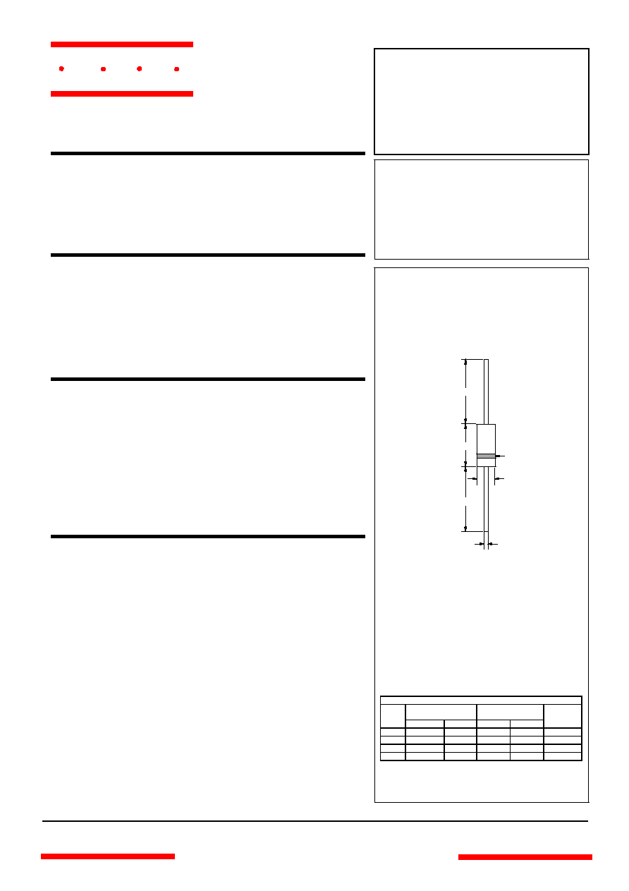
DO-15
A
B
C
D
D
Cathode
Mark
DIMENSIONS
INCHES
MM
DIM
MIN
MAX
MIN
MAX
NOTE
A
.230
.300
5.80
7.60
B
.104
.140
2.60
3.60
C .028 .034 .70 .90
D
1.000
---
25.40
---
www.
mccsemi
.com
omponents
21201 Itasca Street Chatsworth
!"#
$
% !"#
M C C
www.
mccsemi
.com
P6KE6.8 thru P6KE
440A
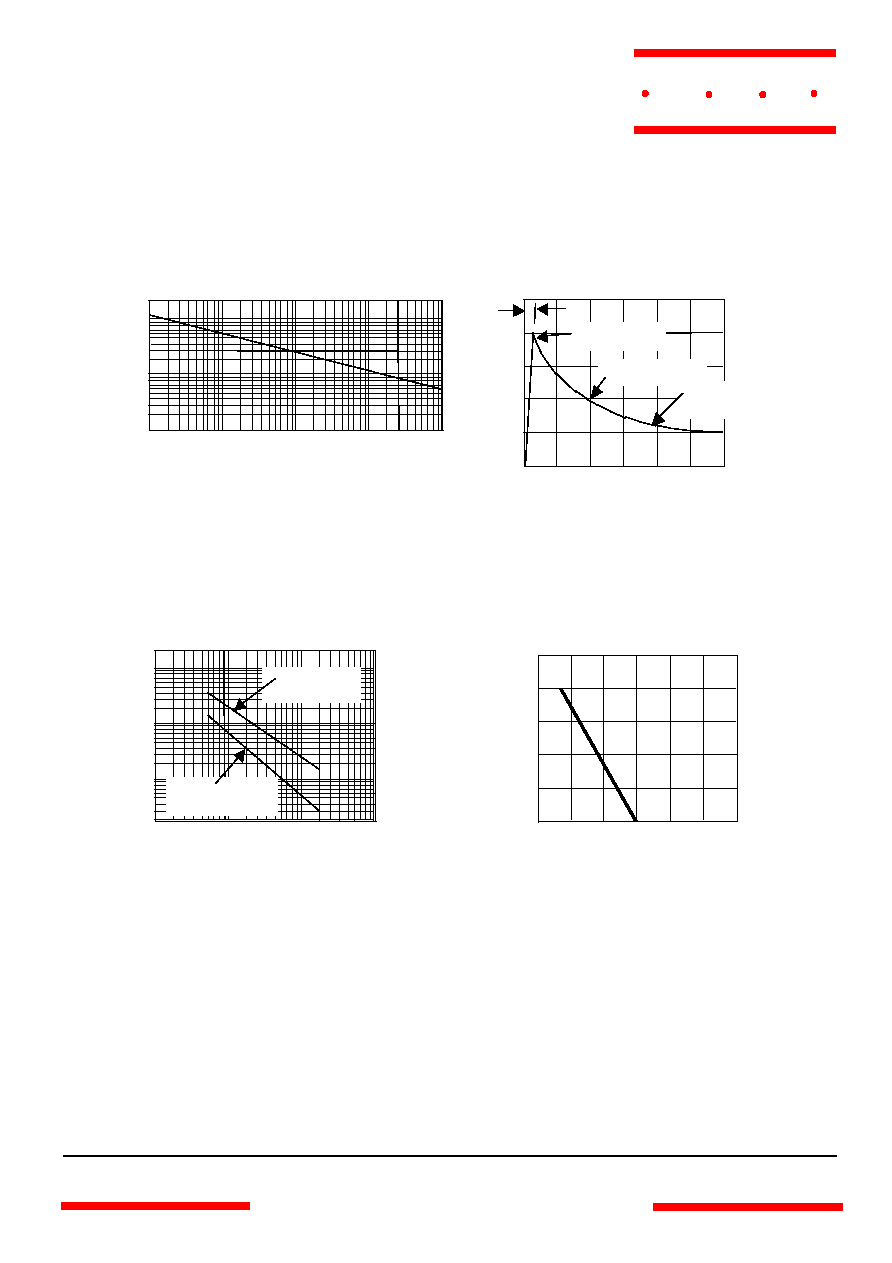
Peak Pulse Power (P
PP
) ≠ versus ≠ Pulse Time (t
P
)
Figure 1
.1
µ
se
c
1
µ
sec
10
µ
sec
100
µ
sec
0
0.1
1.0
10
P
PP -
KW
t
P
1msec
Figure 2 - Pulse Waveform
Peak Pulse Current (% I
PP
) - Versus - Time (t)
msec
0
1
2
3
% I
PP
50
100
Peak Value I
PP
Half Wave I
PP
/2
10 x 1000 Wave as
defined by R.E.A.
Test wave
form
parameters:
t
r
= 10
µ
sec
t
r
M C C
Figure 4 - Derating Curve
Peak Pulse Power (% P
PP
) - Versus - Temperature
∞
C
Temperature
∞
C
0
100
200
300
% P
PP
50
100
Typical Capacitance (pf) ≠ versus ≠ Breakdown voltage
(V )
Figure 3 - Typical Capacitance
0
10
100
1000
10
100
1000
pf
V
BR
10000
Measured at
zero bias
Measured at
standoff voltage

www.
mccsemi
.com
M C C
P6KE75
67.5
75
82.5
1
60.7
5
108
5.5
.105
P6KE75A
71.3
75
78.8
1
64.1
5
103
5.8
.105
P6KE82
73.8
82
90.2
1
66.4
5
118
5.1
.105
P6KE82A
77.9
82
86.1
1
70.1
5
113
5.3
.105
P6KE91
81.9
91
100
1
73.7
5
131
4.5
.106
P6KE91A
86.5
91
95.5
1
77.8
5
125
4.8
.106
P6KE100
90
100
110
1
81
5
144
4.2
.106
P6KE100A
95
100
105
1
85.5
5
137
4.4
.106
P6KE110
99
110
121
1
89.2
5
158
3.8
.107
P6KE110A 105 110 116 1 94 5 152
4.0 .107
P6KE120
108
120
132
1
97.2
5
173
3.5
.107
P6KE120A
114
120
126
1
102
5
165
3.6
.107
P6KE130
117
130
143
1
105
5
187
3.2
.108
P6KE130A
124
130
137
1
111
5
179
3.3
.108
P6KE150
135
150
165
1
121
5
215
2.8
.108
P6KE150A
143
150
158
1
128
5
207
2.9
.108
P6KE160
144
160
176
1
130
5
230
2.6
.108
P6KE160A
152
160
168
1
136
5
219
2.7
.108
P6KE170
153
170
187
1
138
5
244
2.5
.108
P6KE170A
161
170
179
1
145
5
234
2.6
.108
P6KE180
162
180
198
1
146
5
258
2.3
.108
P6KE180A
171
180
189
1
154
5
246
2.4
.108
P6KE200
180
200
220
1
162
5
287
2.1
.108
P6KE200A
190
200
210
1
171
5
274
2.2
.108
MCC
PART NUMBER
BREAKDOWN
VOLTAGE
V
(BR)
@ I
T
(VOLTS)
TEST
CURRENT
I
T
RATED
STANDOFF
VOLTAGE
V
WM
MAXIMUM
REVERSE
LEAKAGE
I
D
@V
WM
MAXIMUM
CLAMPING
VOLTAGE
V
C
@ I
PP
MAXIMUM
PEAK
PULSE
CURRENT
I
PP
MAX. TEMP
COEFFICIENT OF
V
BR
V
(BR)
(TA)
≠55
∞
C TO 100
∞
C
MIN
NOM
MAX
mADC
V
(
µ
A)
V
A
% /
∞
C
P6KE6.8 thru P6KE440A
P6KE
220 198 220 242 1 175 5 344 1.8 .108
P6KE
220A 209 220 231 1 185 5 328 1.9 .108
P6KE
250 225 250 275 1 202 5 360 1.7 .110
P6KE
250A 237 250 263 1 214 5 344 1.8 .110
P6KE
300 270 300 330 1 243 5 430 1.4 .110
P6KE
300A 285 300 315 1 256 5 414 1.5 .110
P6KE
350 315 350 385 1 284 5 504 1.2 .110
P6KE
350A 332 350 368 1 300 5 482 1.3 .110
P6KE
400 360 400 440 1 324 5 574 1.05 .110
P6KE
400A 380 400 420 1 342 5 548 1.1 .110
P6KE
440 396 440 484 1 356 5 631 0.99 .110
P6KE
440A 418 440 462 1 376 5 600 1.04 .110
