1
DESCRIPTION
s
Guaranteed AC parameters over temperature:
∑ f
MAX
> 160MHz (TTL)
∑ < 5.5ns PECL-to-TTL propagation delay
∑ < 1.5ns t
r
/ t
f
; PECL output
∑ < 1.3ns TTL-to-PECL propagation delay
s
Wide temperature range: ≠40
∞
C to +85
∞
C
s
5V power supply
s
Q
TTL
output will default low with inputs left open
or < 1.3V
s
Q
ECL
output will default high with inputs left open
s
Internal PECL input pulldown resistors
s
Available in 8-pin MSOP and SOIC packages
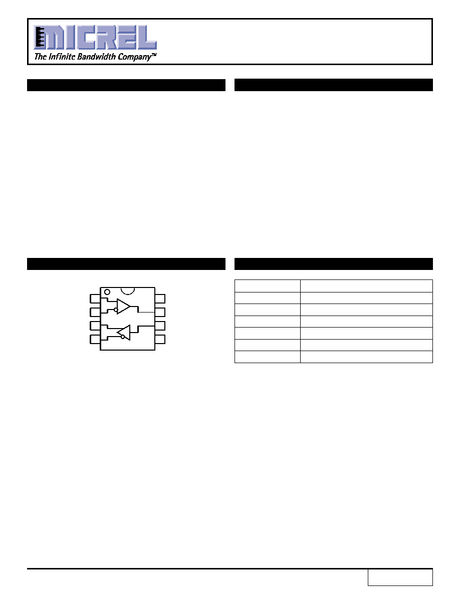
The SY10/100ELT28 is a differential PECL-to-TTL
translator and a TTL-to-differential PECL translator in a
single package. Because PECL (Positive ECL) levels are
used, only +5V and ground are required. The small outline
8-pin package and the dual translation design of the
ELT28 makes it ideal for applications which are sending
and receiving signals across a backplane.
FEATURES
PIN CONFIGURATION/BLOCK DIAGRAM
PIN NAMES
5V TTL-TO-DIFFERENTIAL PECL
AND DIFFERENTIAL PECL-TO-TTL
TRANSLATOR
1
DECL
/DECL
QECL
/QECL
8
VCC
QTTL
DTTL
GND
7
6
5
2
3
4
PECL
TTL
TOP VIEW
(Available in MSOP or SOIC package)
Pin
Function
DTTL
TTL Inputs
QTTL
TTL Outputs
DECL, /DECL
PECL Differential Inputs
QECL, /QECL
PECL Differential Outputs
V
CC
Positive Supply
GND
Ground
SY10ELT28
SY100ELT28
FINAL
Rev.: B
Amendment: /0
Issue Date:
February 2003

2
SY10ELT28
SY100ELT28
Micrel
Symbol
Rating
Value
Unit
V
CC
Power Supply Voltage
≠0.5 to +7.0
V
V
IN
Input Voltage
0 to +6.0
V
I
OUT
PECL Output Current
≠Continuous
50
mA
≠Surge
100
T
A
Operating Temperature Range
≠40 to +85
∞
C
T
store
Storage Temperature Range
≠65 to +150
∞
C
JA
Package Thermal Resistance
≠Still-Air
(SOIC)
160
∞
C/W
(Junction-to-Ambient)
≠500lfpm (SOIC)
109
≠Still-Air
(MSOP)
206
∞
C/W
≠500lfpm (MSOP)
155
JC
Package Thermal Resistance
(SOIC)
39
∞
C/W
(Junction-to-Case)
(MSOP)
39
ABSOLUTE MAXIMUM RATINGS
(1)
T
A
= ≠40
∞
C
T
A
= +25
∞
C
T
A
= +85
∞
C
Symbol
Parameter
Min.
Typ.
Max.
Min.
Typ.
Max.
Min.
Typ.
Max.
Unit
Condition
V
CC
Power Supply Voltage
4.75
5.0
5.5
4.75
5.0
5.5
4.75
5.0
5.5
V
I
CC
Power Supply Current
--
23
40
--
22
40
--
25
40
mA
C
IN
Input Capacitance
(SOIC)
--
--
--
--
0.75
--
--
--
--
pF
(MSOP)
--
--
--
--
1.1
--
--
--
--
pF
DC ELECTRICAL CHARACTERISTICS
(1)
V
CC
= +5V
±
10%; V
EE
= 0V
NOTE:
1. 10/100KELT circuits are designed to meet the DC specifications shown in the above table after thermal equilibrium has been established. The circuit is
in a test socket or mounted on a printed circuit board and traverse airflow greater than 500lfpm is maintained. Input and output parameters vary 1:1 with
V
CC
. V
CC
can vary
±
0.25V.
T
A
= ≠40
∞
C
T
A
= +25
∞
C
T
A
= +85
∞
C
Symbol
Parameter
Min.
Typ.
Max.
Min.
Typ.
Max.
Min.
Typ.
Max.
Unit
Condition
V
OH
Output HIGH Voltage
3920
4010
4110
4020
4105
4190
4090
4185
4280
mV
50
V
CC
≠2V
V
OL
Output LOW Voltage
3050
3200
3350
3050
3210
3370
3050
3227
3405
mV
50
V
CC
≠2V
V
IH
Input HIGH Voltage
3770
--
4110
3870
--
4190
3940
--
4280
mV
(Single-Ended)
V
IL
Input LOW Voltage
3050
--
3500
3050
--
3520
3050
--
3555
mV
(Single-Ended)
V
IHCMR
Input HIGH Voltage
1.2
--
V
CC
1.2
--
V
CC
1.2
--
V
CC
mV
Common Mode Range
(2)
10K PECL DC ELECTRICAL CHARACTERISTICS
(1)
V
CC
= +5.0V
±
10%
NOTES:
1. 10/100KELT circuits are designed to meet the DC specifications shown in the above table after thermal equilibrium has been established. The circuit is
in a test socket or mounted on a printed circuit board and traverse airflow greater than 500lfpm is maintained.
2. V
IHCMR
(Min) varies 1:1 with GND, V
IHCMR
(Max) varies 1:1 with V
CC
.
NOTE:
1. Permanent device damage may occur if ABSOLUTE MAXIMUM RATINGS are exceeded. This is a stress rating only and functional operation is not implied
at conditions other than those detailed in the operational sections of this data sheet. Exposure to ABSOLUTE MAXIMUM RATlNG conditions for extended
periods may affect device reliability.
3
SY10ELT28
SY100ELT28
Micrel
T
A
= ≠40
∞
C
T
A
= +25
∞
C
T
A
= +85
∞
C
Symbol
Parameter
Min.
Typ.
Max.
Min.
Typ.
Max.
Min.
Typ.
Max.
Unit
Condition
V
OH
Output HIGH Voltage
3915
3995
4120
3975
4045
4120
3975
4050
4120
mV
50
V
CC
≠2V
V
OL
Output LOW Voltage
3170
3305
3445
3190
3295
3380
3190
3295
3380
mV
50
V
CC
≠2V
V
IH
Input HIGH Voltage
3835
--
4120
3835
--
4120
3835
--
4120
mV
(Single-Ended)
V
IL
Input LOW Voltage
3190
--
3525
3190
--
3525
3190
--
3525
mV
(Single-Ended)
V
IHCMR
Input HIGH Voltage
2.2
--
V
CC
2.2
--
V
CC
2.2
--
V
CC
V
Common Mode Range
(2)
100K PECL DC ELECTRICAL CHARACTERISTICS
(1)
V
CC
= +5.0V
±
10%
NOTES:
1. 10/100KELT circuits are designed to meet the DC specifications shown in the above table after thermal equilibrium has been established. The circuit is
in a test socket or mounted on a printed circuit board and traverse airflow greater than 500lfpm is maintained.
2. V
IHCMR
(Min) varies 1:1 with GND, V
IHCMR
(Max) varies 1:1 with V
CC
.
T
A
= ≠40
∞
C
T
A
= +25
∞
C
T
A
= +85
∞
C
Symbol
Parameter
Min.
Typ.
Max.
Min.
Typ.
Max.
Min.
Typ.
Max.
Unit
Condition
I
IH
Input HIGH Current
--
10
20
--
--
20
--
--
20
µ
A
V
IN
= 2.7V
--
--
100
--
--
100
--
--
100
µ
A
V
IN
= V
CC
I
IL
Input LOW Current
--
--
≠600
--
--
≠600
--
--
≠600
µ
A
V
IN
= 0.5V
V
IH
Input HIGH Voltage
2.0
--
--
2.0
--
--
2.0
--
--
V
V
IL
Input LOW Voltage
--
--
0.8
--
--
0.8
--
--
0.8
V
V
IK
Input Clamp Diode Voltage
--
--
≠1.2
--
--
≠1.2
--
--
≠1.2
V
I
IK
= ≠18mA
V
OH
Output HIGH Voltage
2.4
2.9
--
2.4
3.4
--
2.4
3.9
--
V
I
OH
= ≠3.0mA
V
OL
Output LOW Voltage
--
0.29
0.5
--
0.26
0.5
--
0.27
0.5
V
I
OL
= 24mA
I
OSC
Output Short-Circuit Current
≠175
--
≠60
≠175
--
≠60
≠175
--
≠60
µ
A
V
O
= 0V
TTL DC ELECTRICAL CHARACTERISTICS
(1)
V
CC
= +5.0V
±
10%
NOTES:
1. 10/100KELT circuits are designed to meet the DC specifications shown in the above table after thermal equilibrium has been established. The circuit is
in a test socket or mounted on a printed circuit board and traverse airflow greater than 500lfpm is maintained.

4
SY10ELT28
SY100ELT28
Micrel
PRODUCT ORDERING CODE
NOTES:
1. f
MAX
is defined as the maximum toggle frequency.
2. V
PP
(Min) is the minimum input swing for which AC parameters are guaranteed.
3. See "Timing Waveform."
TIMING WAVEFORM
Q(0:9)
/Q(0:9)
150mV to 1200mV
T
A
= ≠40
∞
C
T
A
= +25
∞
C
T
A
= +85
∞
C
Symbol
Parameter
Min.
Typ.
Max.
Min.
Typ.
Max.
Min.
Typ.
Max.
Unit
Condition
f
MAX
MaximumFrequency
(1)
PECL
700
--
--
700
--
--
700
--
--
MHz
TTL
160
--
--
160
--
--
160
--
--
MHz
t
PLH
Propagation
DEC L
QTTL
1.5
--
5.5
1.5
--
5.5
1.5
--
5.5
ns
C
L
= 20pF
Delay
DTTL
QECL
0.2
--
1.2
0.2
1.2
1.5
0.2
--
1.35
ns
50
toV
CC
≠2V
t
PHL
Propagation
DEC L
QTTL
1.5
--
5.5
1.5
--
5.5
1.5
--
5.5
ns
C
L
= 20pF
Delay
DTTL
QECL
0.2
--
1.2
0.2
1.2
1.5
0.2
--
1.35
ns
50
toV
CC
≠2V
V
PP
PECL Input VoltageSwing
(2)
200
800
1000
200
800
1000
200
800
1000
mV
(Single-Ended)
(3)
t
r
QECL Output Rise/Fall Times
0.15
--
1.5
0.15
0.3
1.5
0.15
--
1.5
ns
50
to
t
f
(20% to 80%)
V
CC
≠2V
QTTL Output Rise/Fall Times
C
L
= 20pF;
(10% to 90%)
TTL
--
1.0
--
--
0.80
--
--
0.7
--
ns
TTL Output
AC ELECTRICAL CHARACTERISTICS
V
CC
= +5.0V
±
10%
Ordering
Package
Operating
Marking
Code
Type
Range
Code
SY10ELT28KI
(1)
K8-1
Industrial
XL28
SY10ELT28KITR*
(1)
K8-1
Industrial
XL28
SY100ELT28KI
(1)
K8-1
Industrial
XL28
SY100ELT28KITR*
(1)
K8-1
Industrial
XL28
SY10ELT28ZI
(1)
Z8-1
Industrial
XEL28
SY10ELT28ZITR*
(1)
Z8-1
Industrial
XEL28
SY100ELT28ZI
(1)
Z8-1
Industrial
XEL28
SY100ELT28ZITR*
(1)
Z8-1
Industrial
XEL28
Ordering
Package
Operating
Marking
Code
Type
Range
Code
SY10ELT28KC
K8-1
Commercial
XL28
SY10ELT28KCTR*
K8-1
Commercial
XL28
SY100ELT28KC
K8-1
Commercial
XL28
SY100ELT28KCTR*
K8-1
Commercial
XL28
SY10ELT28ZC
Z8-1
Commercial
XEL28
SY10ELT28ZCTR*
Z8-1
Commercial
XEL28
SY100ELT28ZC
Z8-1
Commercial
XEL28
SY100ELT28ZCTR*
Z8-1
Commercial
XEL28
*Tape and Reel
Note 1.
Recommended for new designs.

5
SY10ELT28
SY100ELT28
Micrel
TERMINATION RECOMMENDATIONS
R2
130
R2
130
Z
O
= 50
Z
O
= 50
+5.0V
+5.0V
V
t
= V
CC
--2V
R1
82
R1
82
+5.0V
Figure 1. +5V PECL Parallel Termination≠Thevenin Equivalent
Z
= 50
Z
= 50
50
50
+5.0V
+5.0V
source
destination
R
b
Figure 2. +5V PECL Three-Resistor "Y≠Termination"
Notes:
1. Power-saving alternative to 4-resistor, Thevenin termination.
2. Place termination resistors as close to destination inputs as possible.
3. R
b
resistor sets the DC bias voltage, equal to V
t
. For 5.0V supply, R
b
value is 110
.
6
SY10ELT28
SY100ELT28
Micrel
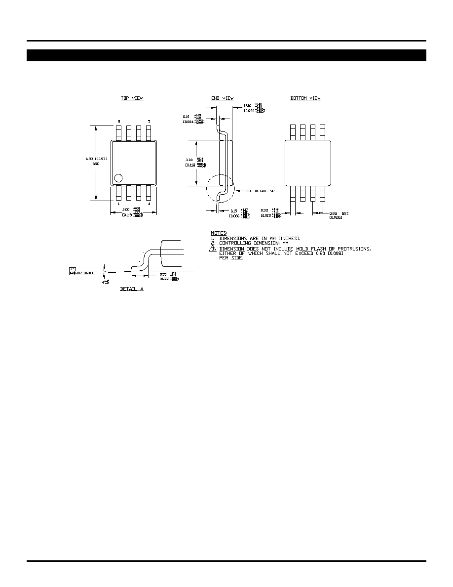
8 LEAD MSOP (K8-1)
Rev. 01

7
SY10ELT28
SY100ELT28
Micrel
8 LEAD SOIC .150" WIDE (Z8-1)
Rev. 03
MICREL, INC.
1849 FORTUNE DRIVE
SAN JOSE, CA 95131
USA
TEL
+ 1 (408) 944-0800
FAX
+ 1 (408) 944-0970
WEB
http://www.micrel.com
The information furnished by Micrel in this datasheet is believed to be accurate and reliable. However, no responsibility is assumed by Micrel for its use.
Micrel reserves the right to change circuitry and specifications at any time without notification to the customer.
Micrel Products are not designed or authorized for use as components in life support appliances, devices or systems where malfunction of a product can
reasonably be expected to result in personal injury. Life support devices or systems are devices or systems that (a) are intended for surgical implant into
the body or (b) support or sustain life, and whose failure to perform can be reasonably expected to result in a significant injury to the user. A Purchaser's
use or sale of Micrel Products for use in life support appliances, devices or systems is at Purchaser's own risk and Purchaser agrees to fully indemnify
Micrel for any damages resulting from such use or sale.
© 2003 Micrel, Incorporated.