DS30292C - page ii
2001 Microchip Technology Inc.
"All rights reserved. Copyright � 2001, Microchip Technology
Incorporated, USA. Information contained in this publication
regarding device applications and the like is intended through
suggestion only and may be superseded by updates. No rep-
resentation or warranty is given and no liability is assumed by
Microchip Technology Incorporated with respect to the accu-
racy or use of such information, or infringement of patents or
other intellectual property rights arising from such use or oth-
erwise. Use of Microchip's products as critical components in
life support systems is not authorized except with express
written approval by Microchip. No licenses are conveyed,
implicitly or otherwise, under any intellectual property rights.
The Microchip logo and name are registered trademarks of
Microchip Technology Inc. in the U.S.A. and other countries.
All rights reserved. All other trademarks mentioned herein are
the property of their respective companies. No licenses are
conveyed, implicitly or otherwise, under any intellectual prop-
erty rights."
Trademarks
The Microchip name, logo, PIC, PICmicro, PICMASTER, PIC-
START, PRO MATE, K
EE
L
OQ
, SEEVAL, MPLAB and The
Embedded Control Solutions Company are registered trade-
marks of Microchip Technology Incorporated in the U.S.A. and
other countries.
Total Endurance, ICSP, In-Circuit Serial Programming, Filter-
Lab, MXDEV, microID, FlexROM, fuzzyLAB, MPASM,
MPLINK, MPLIB, PICDEM, ICEPIC, Migratable Memory,
FanSense, ECONOMONITOR and SelectMode are trade-
marks of Microchip Technology Incorporated in the U.S.A.
Serialized Quick Term Programming (SQTP) is a service mark
of Microchip Technology Incorporated in the U.S.A.
All other trademarks mentioned herein are property of their
respective companies.
� 2001, Microchip Technology Incorporated, Printed in the
U.S.A., All Rights Reserved.
Microchip received QS-9000 quality system
certification for its worldwide headquarters,
design and wafer fabrication facilities in
Chandler and Tempe, Arizona in July 1999. The
Company's quality system processes and
procedures are QS-9000 compliant for its
PICmicro
�
8-bit MCUs, K
EE
L
OQ
�
code hopping
devices, Serial EEPROMs and microperipheral
products. In addition, Microchip's quality
system for the design and manufacture of
development systems is ISO 9001 certified.
2001 Microchip Technology Inc.
DS30292C-page 1
PIC16F87X
Devices Included in this Data Sheet:
Microcontroller Core Features:
� High performance RISC CPU
� Only 35 single word instructions to learn
� All single cycle instructions except for program
branches which are two cycle
� Operating speed: DC - 20 MHz clock input
DC - 200 ns instruction cycle
� Up to 8K x 14 words of FLASH Program Memory,
Up to 368 x 8 bytes of Data Memory (RAM)
Up to 256 x 8 bytes of EEPROM Data Memory
� Pinout compatible to the PIC16C73B/74B/76/77
� Interrupt capability (up to 14 sources)
� Eight level deep hardware stack
� Direct, indirect and relative addressing modes
� Power-on Reset (POR)
� Power-up Timer (PWRT) and
Oscillator Start-up Timer (OST)
� Watchdog Timer (WDT) with its own on-chip RC
oscillator for reliable operation
� Programmable code protection
� Power saving SLEEP mode
� Selectable oscillator options
� Low power, high speed CMOS FLASH/EEPROM
technology
� Fully static design
� In-Circuit Serial Programming
(ICSP)
via two
pins
� Single 5V In-Circuit Serial Programming capability
� In-Circuit Debugging via two pins
� Processor read/write access to program memory
� Wide operating voltage range: 2.0V to 5.5V
� High Sink/Source Current: 25 mA
� Commercial, Industrial and Extended temperature
ranges
� Low-power consumption:
- < 0.6 mA typical @ 3V, 4 MHz
- 20
�
A typical @ 3V, 32 kHz
- < 1
�
A typical standby current
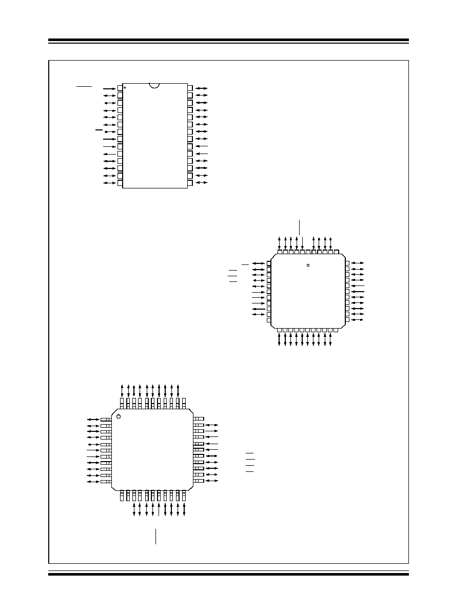
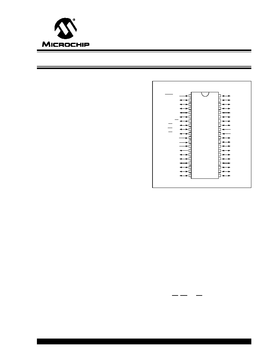
Pin Diagram
Peripheral Features:
� Timer0: 8-bit timer/counter with 8-bit prescaler
� Timer1: 16-bit timer/counter with prescaler,
can be incremented during SLEEP via external
crystal/clock
� Timer2: 8-bit timer/counter with 8-bit period
register, prescaler and postscaler
� Two Capture, Compare, PWM modules
- Capture is 16-bit, max. resolution is 12.5 ns
- Compare is 16-bit, max. resolution is 200 ns
- PWM max. resolution is 10-bit
� 10-bit multi-channel Analog-to-Digital converter
� Synchronous Serial Port (SSP) with SPI
(Master
mode) and I
2
C
(Master/Slave)
� Universal Synchronous Asynchronous Receiver
Transmitter (USART/SCI) with 9-bit address
detection
� Parallel Slave Port (PSP) 8-bits wide, with
external RD, WR and CS controls (40/44-pin only)
� Brown-out detection circuitry for
Brown-out Reset (BOR)
� PIC16F873
� PIC16F874
� PIC16F876
� PIC16F877
RB7/PGD
RB6/PGC
RB5
RB4
RB3/PGM
RB2
RB1
RB0/INT
V
DD
V
SS
RD7/PSP7
RD6/PSP6
RD5/PSP5
RD4/PSP4
RC7/RX/DT
RC6/TX/CK
RC5/SDO
RC4/SDI/SDA
RD3/PSP3
RD2/PSP2
MCLR/V
PP
RA0/AN0
RA1/AN1
RA2/AN2/V
REF
-
RA3/AN3/V
REF
+
RA4/T0CKI
RA5/AN4/SS
RE0/RD/AN5
RE1/WR/AN6
RE2/CS/AN7
V
DD
V
SS
OSC1/CLKIN
OSC2/CLKOUT
RC0/T1OSO/T1CKI
RC1/T1OSI/CCP2
RC2/CCP1
RC3/SCK/SCL
RD0/PSP0
RD1/PSP1
1
2
3
4
5
6
7
8
9
10
11
12
13
14
15
16
17
18
19
20
40
39
38
37
36
35
34
33
32
31
30
29
28
27
26
25
24
23
22
21
P
I
C16
F
877
/874
PDIP
28/40-Pin 8-Bit CMOS FLASH Microcontrollers