Document Outline
- General-purpose Relay
- Ordering Information
- Accessories (Order Separately)
- Specifications
- Coil Ratings
- Contact Ratings
- Characteristics
- Life Expectancies Under Real Loads
- Approved by Standards
- Engineering Data
- Maximum Switching Capacity
- Life Expectancy
- Dimensions
- Relays with Solder Terminals
- Relays with PCB Terminals
- Upper-mounting Relays
- Mounting Height with Socket
- Sockets
- Safety Standards for Sockets
- Precautions
1
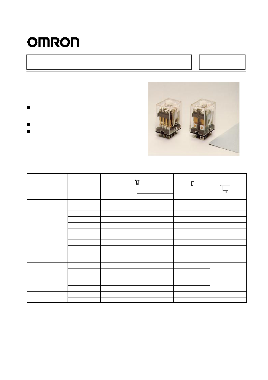
General-purpose Relay
MY
An Improved Miniature Power Relay
with Many Models for Sequence Control
and Power Applications
A wide range of relay variations including ones with
operation indicators, high-capacity capability,
built-in diodes, etc.
Arc barrier standard on 3- and 4-pole relays.
Withstand voltage: 2,000 VAC.
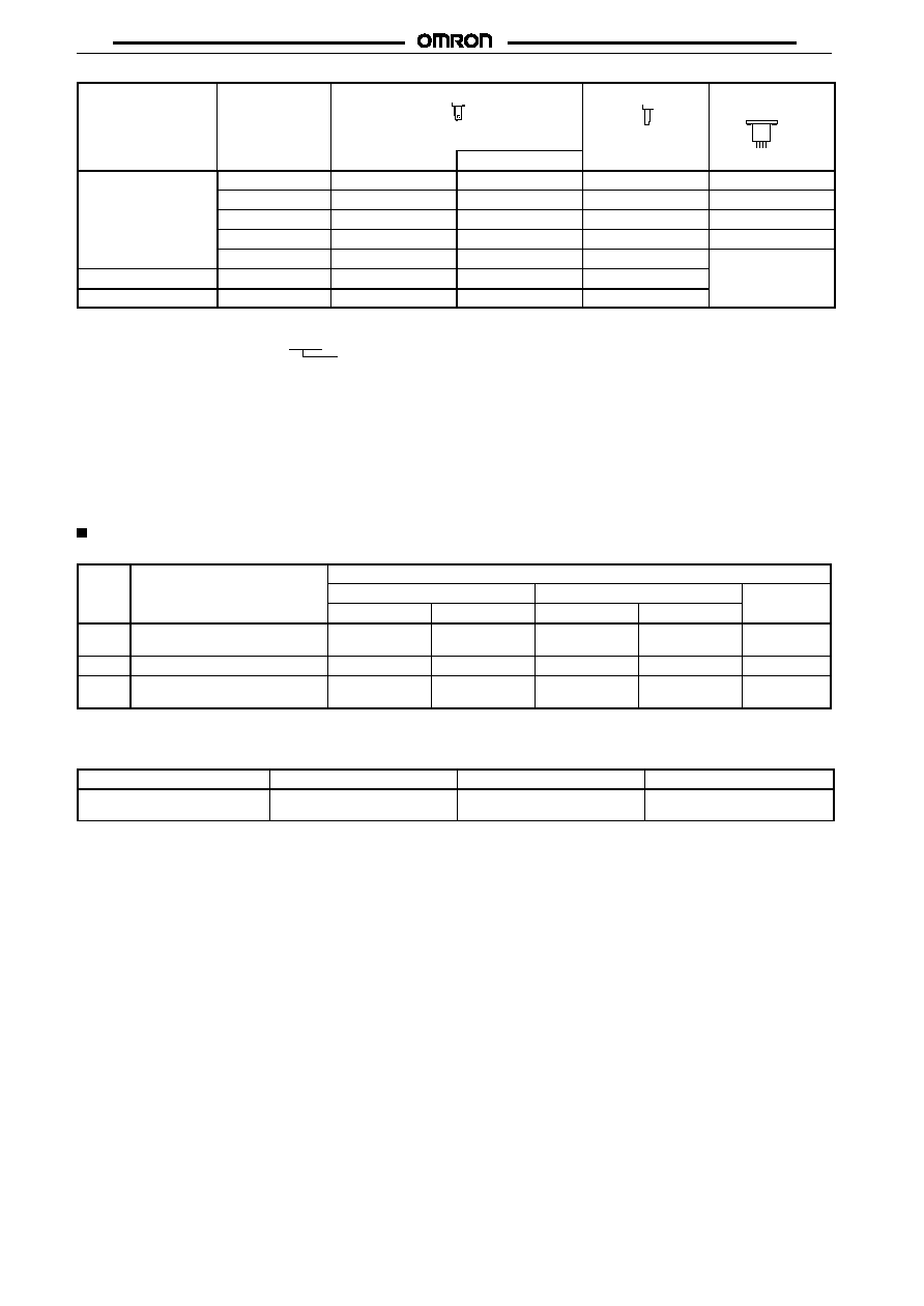
Ordering Information
Type
Contact form
Plug-in socket/solder terminals
PCB terminals
Upper-mounting/
solder terminals
With indicator
Standard
SPDT
*MY1
≠≠≠
*MY1-02
MY1F
DPDT
MY2
MY2N
MY2-02
MY2F
DPDT (bifurcated)
MY2Z
MY2ZN
MY2Z-02
MY2ZF
3PDT
MY3
MY3N
MY3-02
MY3F
4PDT
MY4
MY4N
MY4-02
MY4F
4PDT (bifurcated)
MY4Z
MY4ZN
MY4Z-02
MY4ZF
With built-in diode
DPDT
MY2-D
MY2N-D2
≠≠≠**
≠≠≠
(DC only)
DPDT (bifurcated)
MY2Z-D
MY2ZN-D2
≠≠≠
≠≠≠
3PDT
MY3-D
MY3N-D2
≠≠≠
≠≠≠
4PDT
MY4-D
MY4N-D2
≠≠≠
≠≠≠
4PDT (bifurcated)
MY4Z-D
MY4ZN-D2
≠≠≠
≠≠≠
With built-in CR
DPDT
MY2-CR
MY2N-CR
≠≠≠
Not available.
(AC only)
DPDT (bifurcated)
MY2Z-CR
≠≠≠
≠≠≠
3PDT
MY3-CR
≠≠≠
≠≠≠
4PDT
MY4-CR
MY4N-CR
≠≠≠
4PDT (bifurcated)
MY4Z-CR
≠≠≠
≠≠≠
With test button
DPDT
MY2I4
MY2I4N
≠≠≠
≠≠≠
4PDT
MY4I4
MY4I4N
≠≠≠
≠≠≠
MY
MY
2
Type
Upper-mounting/
solder terminals
PCB terminals
Plug-in socket/solder terminals
Contact form
With indicator
High-humidity
DPDT
MY2-TU
≠≠≠
≠≠≠
≠≠≠
DPDT (bifurcated)
MY2Z-TU
≠≠≠
≠≠≠
≠≠≠
3PDT
MY3-TU
≠≠≠
≠≠≠
≠≠≠
4PDT
MY4-TU
MY4N-TU
≠≠≠
≠≠≠
4PDT (bifurcated)
MY4Z-TU
≠≠≠
≠≠≠
Not available.
High-capacity (7 A)
DPDT
MY2-Y
MY2N-Y
≠≠≠
High-sensitivity
3PDT
MYC3
Not available
MYC3-02
Rated coil voltage
Note:
1. When ordering, add the rated coil voltage to the model number. Rated coil voltages are given in the coil ratings table.
Example: MY2, 6 VAC
*2. Models mark with an asterisk are not available with international safety standard ratings.
3. Add "-G" to the model number if mounting studs are required (e.g., MY4-G).
4. The standard contacts for MY2Z-series Relays and for the MY4Z are gold-plated.
**5. Models denoted by "≠≠≠" will be manufactured upon request. Ask your OMRON representative.
6. The following variations are also available.
Plastic-sealed relays (MYQ4):
See page 46.
Latching relays (MY2K):
See page 51.
Hermetically sealed relays (MY4H): Ask your OMRON representative.
Accessories (Order Separately)
Sockets
Poles
Front-mounting socket
Back-mounting socket
(DIN-rail/screw mounting)
Solder terminals
Wire-wrap terminals
PCB
W/ clip
W/o clip
W/ clip
W/o clip
terminals
1 or 2
PYF08A-E, PYF08A,
PYF08A-N (finger protection)
PY08
PY08-Y1
PY08QN
PY08QN-Y1
PY08≠02
3
PYF11A-E, PYF11A
PY11
PY11-Y1
PY11QN
PY11QN-Y1
PY11-02
4
PYF14A-E, PYF14A
PYF14A-N (finger protection)
PY14
PY14-3*
PY14-Y1
PY14QN
PY14QN-Y1
PY14-02
Note:
*1. Equipped with operation check terminal.
2. The PYF08A(-E), PYF11A(-E), and PYF14A(-E) have been approved as individual sockets by UL S08 and CSA C22.2.
Mounting Plates for Sockets
Socket model
For 1 socket
For 18 sockets
For 36 sockets
PY08, PY11, PY14, PY08QN(2),
PY11QN(2), PY14QN(2)
PYP-1
PYP-18
PYP-36
Note:
PYP-18 and PYP-36 can be cut into any desired length in accordance with the number of sockets.
MY
MY
3
Socket Hold-down Clip Pairing
Relay type
Poles
Front-connecting
sockets
Back-connecting sockets
(rail-/screw-mounted)
Solder/wire-wrap terminals
PCB terminals
Socket
Clip
Socket
Clip
Socket
Clip
Standard, bifurcated contacts, operation
indicator, built-in diode, high-capacity,
high-sensitivity, or high-humidity
1, 2
PYF08A-N,
PYF08A-E,
PYF08A
PYC-A1
PY08(QN)
PYC-P
PY08(QN)
PYC-P
g
y,
g
y
3
PYF11A
PY11(QN)
PY11(QN)
4
PYF14A-N,
PYF14A-E,
PYF14A
PY14(QN)
PY14(QN)
MY2N-D4
4
PYF14A-N,
PYF14A-E,
PYF14A
Y92H-3
PY14(QN)
PYC-1
PY08(QN)
PYC-1
Test button
1, 2
PYF08A-N,
PYF08A-E,
PYF08A
PYC-A1
PY08(QN)
PYC-P2
PY08(QN)
PYC-P2
3
PYF11A
PY11(QN)
PY11(QN)
4
PYF14A-N,
PYF14A-E,
PYF14A
PY14(QN)
PY14(QN)
CR circuit
1, 2
PYF08A-N,
PYF08A-E,
PYF08A
Y92H-3
PY08(QN)
PYC-1
PY08(QN)
PYC-1
3
PYF11A
PY11(QN)
PY11(QN)
4
PYF14A-N,
PYF14A-E,
PYF14A
PY14(QN)
PY14(QN)
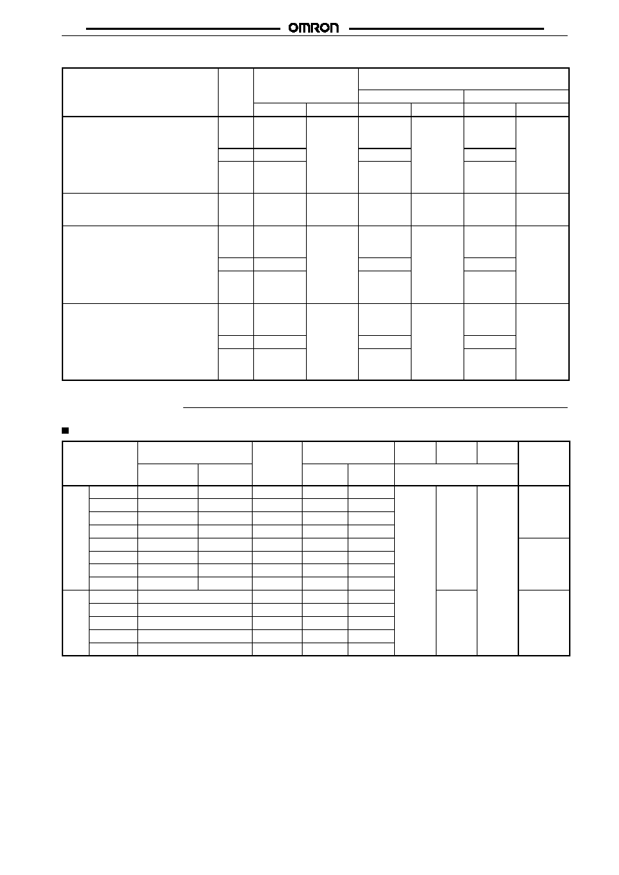
Specifications
Coil Ratings
Rated voltage
Rated current
Coil
resistance
Inductance
(reference value)
Must
operate
Must
release
Max.
voltage
Power
consum.
(A
)
50 Hz
60 Hz
resistance
Arm.
OFF
Arm. ON
% of rated voltage
consum.
(Approx.)
AC
6 V
214.1 mA
183 mA
12.2
0.04 H
0.08 H
80%
30%
110%
1.0 to
1 2 VA
12 V
106.5 mA
91 mA
46
0.17 H
0.33 H
max.
min.
1.2 VA
(60 Hz)
24 V
53.8 mA
46 mA
180
0.69 H
1.30 H
(60 Hz)
50 V
25.7 mA
22 mA
788
3.22 H
5.66 H
100/110 V
11.7/12.9 mA
10/11 mA
3,750
14.54 H
24.6 H
0.9 to
1 1 VA
110/120 V
9.9/10.8 mA
8.4/9.2 mA
4,430
19.20 H
32.1 H
1.1 VA
(60 Hz)
200/220 V
6.2/6.8 mA
5.3/5.8 mA
12,950
54.75 H
94.07 H
(60 Hz)
220/240 V
4.8/5.3 mA
4.2/4.6 mA
18,790
83.50 H
136.40 H
DC
6 V
150 mA
40
0.17 H
0.33 H
10%
0.9 W
12 V
75 mA
160
0.73 H
1.37 H
min.
24 V
36.9 mA
650
3.20 H
5.72 H
48 V
18.5 mA
2,600
10.60 H
21.00 H
100/110 V
9.1/10 mA
11,000
45.60 H
86.20 H
Note:
See notes under next table on next page.
MY
MY
4
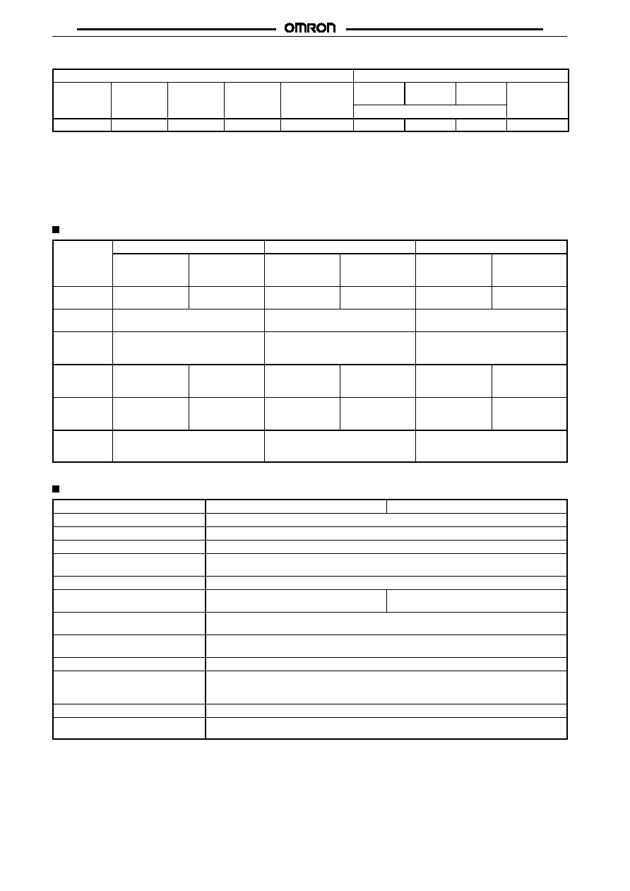
High-sensitivity Relays
Power supply ratings
Input ratings
Voltage
Current
Coil
resistance
Max.
voltage*
Power consum.
Input
voltage
Must
operate
Must
release
Power
consum.
% of rated voltage
24 VDC
36.9 mA
650 W
110%
Approx. 900 mW
2 to 12 V
2 V max.
1 V min.
0.5 to 52 mW
Note:
1. The rated current and coil resistance are measured at a coil temperature of 23
∞
C with tolerances of +15%/≠20% for rated currents
and
±
15% for DC coil resistance.
2. Performance characteristic data are measured at a coil temperatures of 23
∞
C.
3. The must operate and must release voltages for High-sensitivity Relays was measured at the rated power supply voltage.
4. AC coil resistance and impedance are provided as reference values (at 60 Hz).
5. Power consumption drop was measured for the above data. When driving transistors, check leakage current and connect a bleeder
resistor if required.
Contact Ratings
Item
Single-, double- or three-pole
Four-pole and High-sensitivity
High-capacity
Resistive load
(cos
f
= 1)
Inductive load
(cos
f
=0.4,
L/R=7 ms)
Resistive load
(cos
f
= 1)
Inductive load
(cos
f
=0.4,
L/R=7 ms)
Resistive load
(cos
f
= 1)
Inductive load
(cos
f
=0.4,
L/R=7 ms)
Rated load
5 A, 220 VAC
5 A, 24 VDC
2 A, 220 VAC
2 A, 24 VDC
3 A, 220 VAC
3 A, 24 VDC
0.8 A, 220 VAC)
1.5 A, 24 VDC
7 A, 220 VAC
7 A, 24 VDC
3.5 A, 220 VAC
3.5 A, 24 VDC
Carry
current
5 A
3 A
7 A
Max.
switching
voltage
250 VAC
125 VDC
250 VAC
125 VDC
250 VAC
125 VDC
Max.
switching
current
5 A
5 A
3 A
3 A
7 A
7 A
Max.
switching
capacity
1,100 VA
120 W
440 VA
48 W
660 VA
72 W
176 VA
36 W
1,540 VA
168 W
770 VA
84 W
Min.
permissible
load*
Standard type: 100 mA, 5 VDC
Bifurcated type: 100
µ
A, 1 VDC
Standard and high sensitivity types: 1
mA, 1 VDC
Bifurcated type: 100
µ
A, 1 VDC
≠≠≠
*Note: P level:
60
= 0.1 x 10
-6
/operation, reference value
Characteristics
Item
All relays but High-sensitivity Relays
High-sensitivity Relays
Contact resistance
50 m
max.
Operate time
20 ms max.
Release time
20 ms max.
Max. operating frequency
Mechanical: 18,000 operations/hr
Electrical:
1,800 operations/hr (under rated load)
Insulation resistance
1,000 M
min. (at 500 VDC)
Dielectric withstand voltage
2,000 VAC, 50/60 Hz for 1 min (1,000 VAC
between contacts of same polarity)
1,500 VAC, 50/60 Hz for 1 min (1,000 VAC
between contacts of same polarity)
Vibration resistance
Destruction: 10 to 55 Hz, 1.0-mm double amplitude
Malfunction: 10 to 55 Hz, 1.0-mm double amplitude
Shock resistance
Destruction: 1,000 m/s
2
(approx. 100G)
Malfunction: 200 m/s
2
(approx. 20G)
Life expectancy
See following table.
Ambient operating temperature*
Single- and double-pole standard, bifurcated-contact, test-button, and high-humidity relays:
≠55
∞
C to 70
∞
C (with no icing)
All other relays: ≠55
∞
C to 60
∞
C (with no icing)
Ambient operating humidity
35% to 85%
Weight
Approx. 85 g
Note:
The values given above are initial values.
MY
MY
5
Life Expectancy Characteristics
Relays
Mechanical life
(at 18,000 operations/hr)
Electrical life
(at 1,800 operations/hr under rated load)
Normal, High-humidity, With test button (except relays
with operation indicator), With CR
AC 50,000,000 operations min.
DC: 100,000,000 operations min.
1-,2-,3-pole: 500,000 operations min.
4-pole:
200,000 operations min.
High-capacity
AC 50,000,000 operations min.
DC: 100,000,000 operations min.
500,000 operations min.
With operation indicator or built-in diode
AC 50,000,000 operations min.
DC: 100,000,000 operations min.
1-,2-,3-pole: 500,000 operations min.
4-pole:
200,000 operations min.
With bifurcated contacts
2-pole: 50,000,000 operations min.
4-pole: 20,000,000 operations min.
2-pole: 200,000 operations min.
4-pole: 100,000 operations min.
High-sensitivity
100,000,000 operations min.
200,000 operations min.
Note:
See following tables for real load life expectancies.
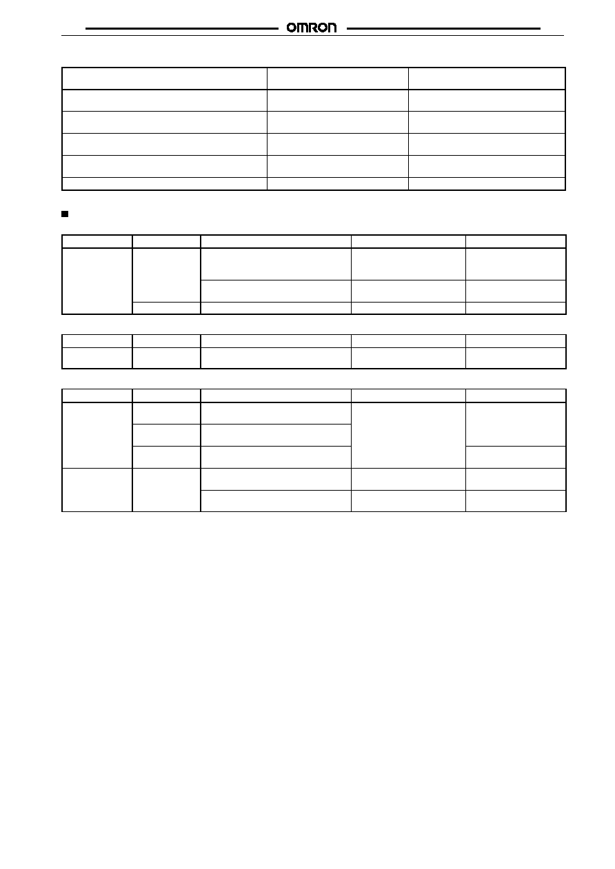
Life Expectancies Under Real Loads
MY2
Rated voltage
Load type
Conditions
Operating frequency
Electrical life
100 VAC
AC motor
50 W, 100 VAC single-phase with
2.8-A inrush current, 0.4-A carry
current
ON for 2 s, OFF for 30 s
100,000 operations
50 W, 100 VAC single-phase with
1.6-A inrush current, 1-A carry current
ON for 1 s, OFF for 30 s
300,000 operations
AC solenoid
24 W with 1-A carry current
ON for 1.5 s, OFF for 1.5 s
4,000,000 operations
MY2E
Rated voltage
Load type
Conditions
Operating frequency
Electrical life
24 VDC
AC lamp
300 W with 50-A inrush current, 3-A
carry current
ON for 5 s, OFF for 55 s
55,000 operations
MY4
Rated voltage
Load type
Conditions
Operating frequency
Electrical life
100 VAC
AC solenoid
50 VA with 2-A inrush current, 0.7A
carry current
ON for 1 s, OFF for 3 s
25,000 operations
DC magnetic
switch
25 W with L/R = 40 ms , 0.2-A carry
current
AC magnetic
switch
35 VA with 1.5-A inrush current,
0.35-A carry current
500,000 operations
24 VDC
DC solenoid
40 W with L/R = 10 ms, 1.6-A carry
current
ON for 0.5 s, OFF for 1.5 s
5,000,000 operations
30 W with L/R = 10 ms with 0.34-A
carry current
ON for 0.5 s, OFF for 1.5 s
6,000,000 operations