AT790
AT1029
AT790 & AT1029
Typical Performance Data
Splitter Electrical Specifications
Features
∑ cellular
∑ UHF/VHF receivers/transmitters
∑ low insertion loss, 0.3 dB typ.
∑ excellent amplitude unbalance, 0.1 dB typ.
∑ very good phase unbalance, 1.0 deg. typ.
∑ temperature stable, BLUE CELLTM base
∑ solder plated leads for excellent solderability
∑ small size
∑ low cost
∑ patent pending
Applications
L
Typ. Min.
M
Typ. Min.
U
Typ. Min.
FREQ.
RANGE
(MHz)
PHASE
UNBALANCE
(Degrees)
L
Max.
U
Max.
M
Max.
ISOLATION
(dB)
INSERTION LOSS (dB)
ABOVE 3.0 dB
L
Typ. Max.
M
Typ. Max.
U
Typ. Max.
AMPLITUDE
UNBALANCE
(dB)
L
Max.
U
Max.
M
Max.
f
L
-f
U
5-1000
29
20
25
18
21
16
0.3
0.7
0.3
0.8
0.5
1.4
3
3
5
0.6
0.5
0.5
Frequency
(MHz)
Insertion Loss
(dB)
S-1
Amplitude
Unbalance
(dB)
Isolation
(dB)
VSWR
S
(dB)
S-2
VSWR
1
VSWR
2
Phase
Unbalance
(deg.)
L = low range [f
L
to 10 f
L
]
M = mid range [10 f
L
to f
U
/2] U = upper range [f
U
/2 to f
U
]
5.00
3.25
3.12
0.13
30.21
0.41
1.03
1.17
1.14
7.00
3.24
3.11
0.13
31.41
0.32
1.02
1.16
1.12
10.00
3.26
3.13
0.13
32.34
0.13
1.02
1.15
1.12
50.00
3.26
3.15
0.12
31.93
0.06
1.02
1.14
1.11
70.00
3.28
3.16
0.12
31.37
0.07
1.03
1.14
1.11
100.00
3.29
3.18
0.11
30.43
0.12
1.03
1.13
1.10
200.00
3.34
3.24
0.10
28.05
0.20
1.05
1.12
1.10
300.00
3.38
3.30
0.08
26.00
0.24
1.06
1.11
1.09
400.00
3.39
3.34
0.05
24.32
0.26
1.07
1.09
1.08
500.00
3.45
3.44
0.02
23.24
0.28
1.08
1.07
1.07
600.00
3.48
3.50
0.02
21.78
0.28
1.10
1.05
1.06
700.00
3.45
3.52
0.07
21.08
0.21
1.10
1.02
1.05
800.00
3.47
3.59
0.12
20.74
0.09
1.09
1.03
1.06
900.00
3.49
3.67
0.18
20.62
0.06
1.08
1.06
1.08
1000.00
3.52
3.76
0.24
20.71
0.27
1.06
1.10
1.11
No Leads
CASE STYLE:AT790
PRICE: $2.49 ea. QTY (25)
$1.69 ea. QTY (1000)
Leads
CASE STYLE:AT1029
PRICE: $2.64 ea. QTY (25)
$1.84 ea. QTY (1000)
SBTC-2-10
NEW!
SBTC-2-10L
Maximum Ratings
Pin Connections
SUM PORT
6
PORT 1
3
PORT 2
4
GROUND
1,2
NOT USED
5
Operating Temperature
-40∞C to 85∞C
Storage Temperature
-55∞C to 100∞C
Power Input (as a splitter)
0.5W max.
Internal Dissipation
0.125W max.
Demo Board MCL P/N: TB-274
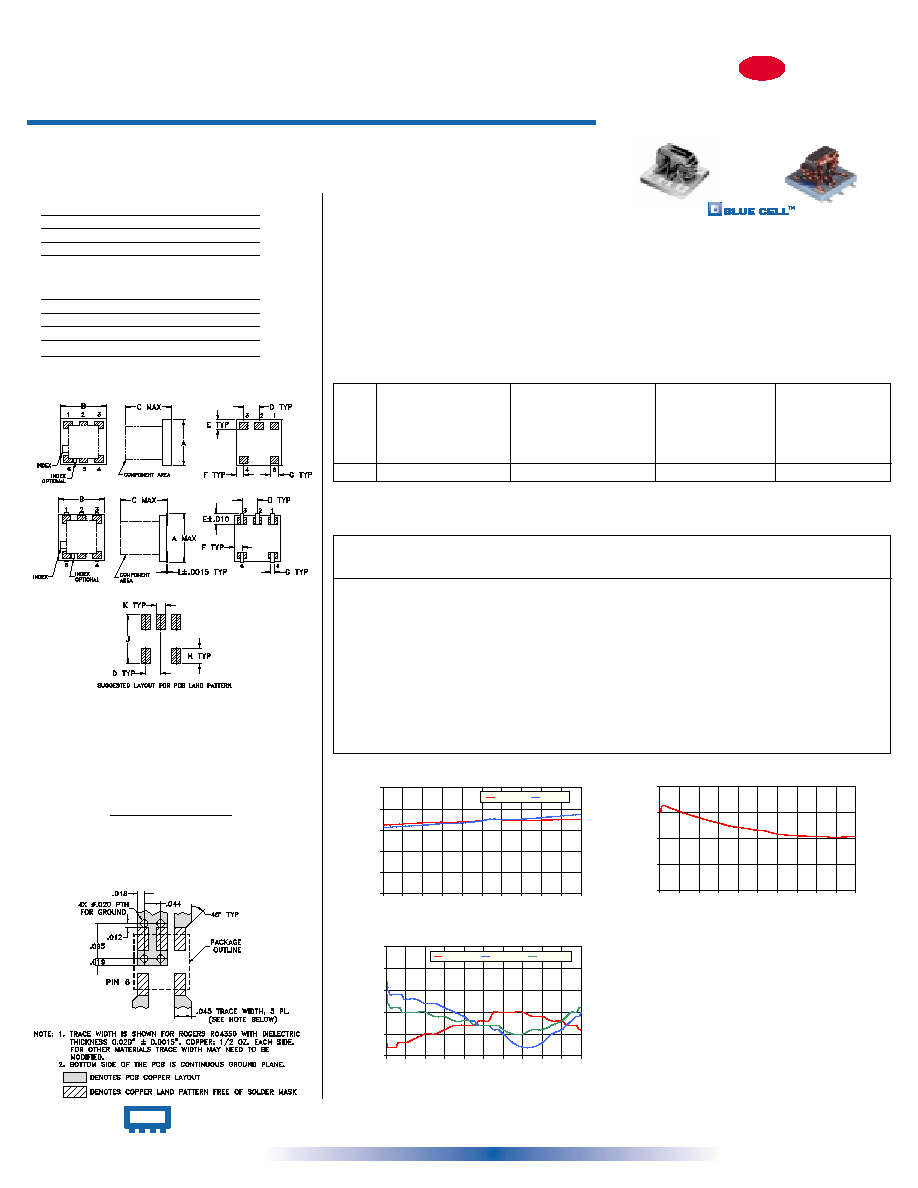
Suggested PCB Layout (PL-152)
Outline Drawing
Reflow Solder Assembly
Silver-bearing solder (Sn/Pb/Ag 62/36/2%) is recommended;
however, tin-lead eutectic (Sn/Pb 63/37%) may be used.
For temperature profiles, see Application Note AN-40-004
AT1029
A
B
C
D
E
F
G
H
J
K
L
wt.
.166 .150 .155 .050 .037 .025 .012 .060 .184 .030 .004 grams
4.22 3.81 3.94 1.27 0.94 0.64 0.30 1.52 4.67 0.76 0.10
.10
AT790
A
B
C
D
E
F
G
H
J
K
wt.
.150 .150 .150 .050 .030 .025 .028 .050 .160 .030
grams
3.81 3.81 3.81 1.27 0.76 0.64 0.71 1.27 4.06 0.76
.10
Outline Dimensions ( )
inch
mm
REV. D
M89618
SBTC-2-10
ED-9227
SBTC-2-10L ED-9915D/2
WZ/TD/CP
040212
2 Way-0∞ 50
5 to 1000 MHz
Power Splitter/Combiners
Surface Mount
SBTC-2-10L
ISOLATION
0
10
20
30
40
0
100
200
300
400
500
600
700
800
900 1000
FREQUENCY (MHz)
ISOLATION (dB)
at RF level of -10 dBm
SBTC-2-10L
VSWR
1.00
1.05
1.10
1.15
1.20
1.25
0
100
200
300
400
500
600
700
800
900 1000
FREQUENCY (MHz)
VSWR
#S-VSWR
#1-VSWR
#2-VSWR
at RF level of -10 dBm
SBTC-2-10L
INSERTION LOSS
0.0
1.0
2.0
3.0
4.0
5.0
0
100
200
300
400
500
600
700
800
900 1000
FREQUENCY (MHz)
INSERTION LOSS (dB)
S-1(dB)
S-2(dB)
at RF level of -10 dBm
INTERNET http://www.minicircuits.com
P.O. Box 350166, Brooklyn, New York 11235-0003 (718) 934-4500 Fax (718) 332-4661
Distribution Centers
NORTH AMERICA 800-654-7949 ∑ 417-335-5935 ∑ Fax 417-335-5945 ∑ EUROPE 44-1252-832600 ∑ Fax 44-1252-837010
Mini-Circuits
Æ
ISO 9001 CERTIFIED