Frequency
(MHz)
Mainline Loss
(dB)
In-Out
Coupling
(dB)
In-Cpl
Directivity
(dB)
In
Return Loss
(dB)
Out
Cpl
Typical Performance Data
Bi-Directional Coupler Electrical Specifications
Maximum Ratings
Coaxial Connections
INPUT
1
OUTPUT
4
COUPLED (forward)
2
COUPLED (reverse)
3
Operating Temperature
-55∞C to 100∞C
Storage Temperature
-55∞C to 100∞C
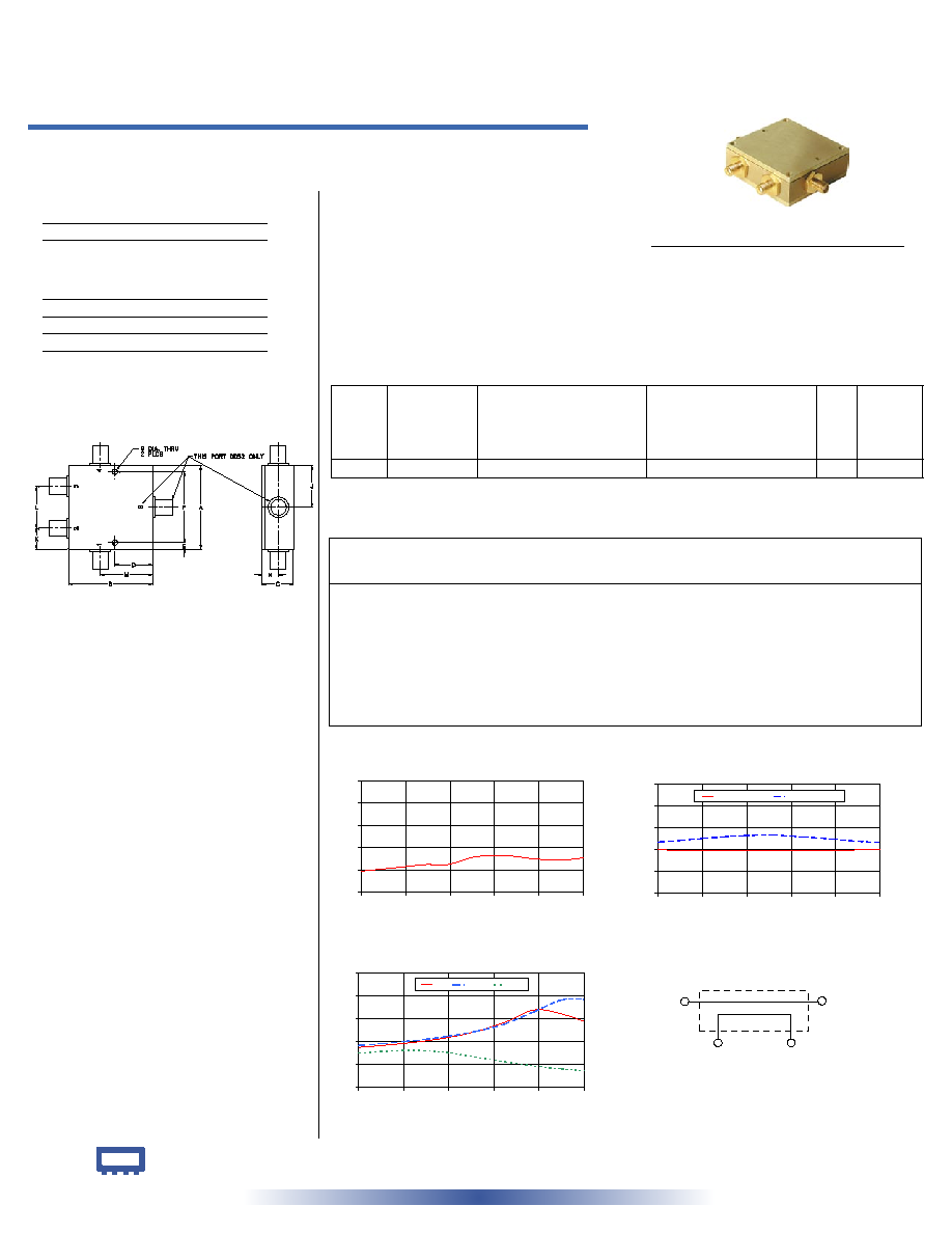
Outline Drawing
Outline Dimensions ( )
inch
mm
ZABDC20-2400
MAINLINE LOSS
0.0
0.2
0.4
0.6
0.8
1.0
1500
1680
1860
2040
2220
2400
FREQUENCY (MHz)
MAINLINE
LOSS
(dB)
at RF level of -10 dBm
ZABDC20-2400
COUPLING & DIRECTIVITY
0
10
20
30
40
50
1500
1680
1860
2040
2220
2400
FREQUENCY (MHz)
C
O
U
P
L
I
N
G
&
D
I
R
E
C
T
I
V
I
T
Y
(
d
B
)
COUPLING
DIRECTIVITY
at RF level of -10 dBm
ZABDC20-2400
ZABDC20-2400
RETURN LOSS
10
20
30
40
50
60
1500
1680
1860
2040
2220
2400
FREQUENCY (MHz)
RETURN
LOSS
(dB)
IN
OUT
CPL
at RF level of -10 dBm
electrical schematic
CPL
FORWARD
CPL
REVERSE
IN
OUT
50 1500 to 2400 MHz
Bi-Directional Coupler
REV. OR
M95663
ZABDC20-2400
WP/TD/CP
060726
Coaxial
A
B
C
D
E
F
G
2.00
2.00
.75
.90
.156
1.688
.125
50.80
50.80
19.05
22.86
3.96
42.88
3.18
H
J
K
L
M
wt
.38
---
.50
1.00
1.25
grams
9.65
---
12.70
25.40
31.75
225.00
Features
∑ excellent directivity, 25 dB typ.
∑ low insertion loss, 0.3 dB typ.
∑ high power, up to 10W
∑ rugged shielded case
Applications
∑ PCS/DCS/UMTS
∑ power leveling & monitoring
∑ VSWR measurement
INTERNET
http://www.minicircuits.com
P.O. Box 350166, Brooklyn, New York 11235-0003 (718) 934-4500 Fax (718) 332-4661
Distribution Centers NORTH AMERICA 800-654-7949 ∑ 417-335-5935 ∑ Fax 417-335-5945 ∑ EUROPE 44-1252-832600 ∑ Fax 44-1252-837010
Mini-Circuits
Æ
Mini-Circuits ISO 9001 & ISO 14001 Certified
CASE STYLE: DD477
Connectors Model
Price
Qty.
SMA
ZABDC20-2400-S $89.95 ea. (1-9)
1500.00
0.19
19.90
23.45
27.51
28.35
24.98
1588.00
0.21
19.75
24.21
28.25
29.14
25.69
1676.00
0.23
19.63
25.06
29.19
30.06
26.19
1764.00
0.25
19.59
25.82
30.29
31.05
26.11
1852.00
0.25
19.56
26.41
31.74
32.30
25.22
1964.00
0.32
19.62
26.62
34.28
34.41
23.34
2084.00
0.33
19.65
25.86
38.45
37.76
21.21
2202.00
0.30
19.71
24.82
43.89
43.16
19.38
2312.00
0.29
19.85
23.81
42.07
48.30
18.05
2400.00
0.31
19.93
23.26
38.87
48.51
17.31
1. Mainline loss includes theoretical power loss at coupled port.
FREQ.
RANGE
(MHz)
COUPLING
(dB)
MAINLINE LOSS
1
(dB)
DIRECTIVITY
(dB)
VSWR
(:1)
POWER
INPUT
(W)
f
L
-f
U
Nom.
Flatness
Typ. Max.
Typ. Min.
Typ.
Max.
1500-2400 19.5±1.0
±1.0
0.3
0.5
25
18
1.2
10