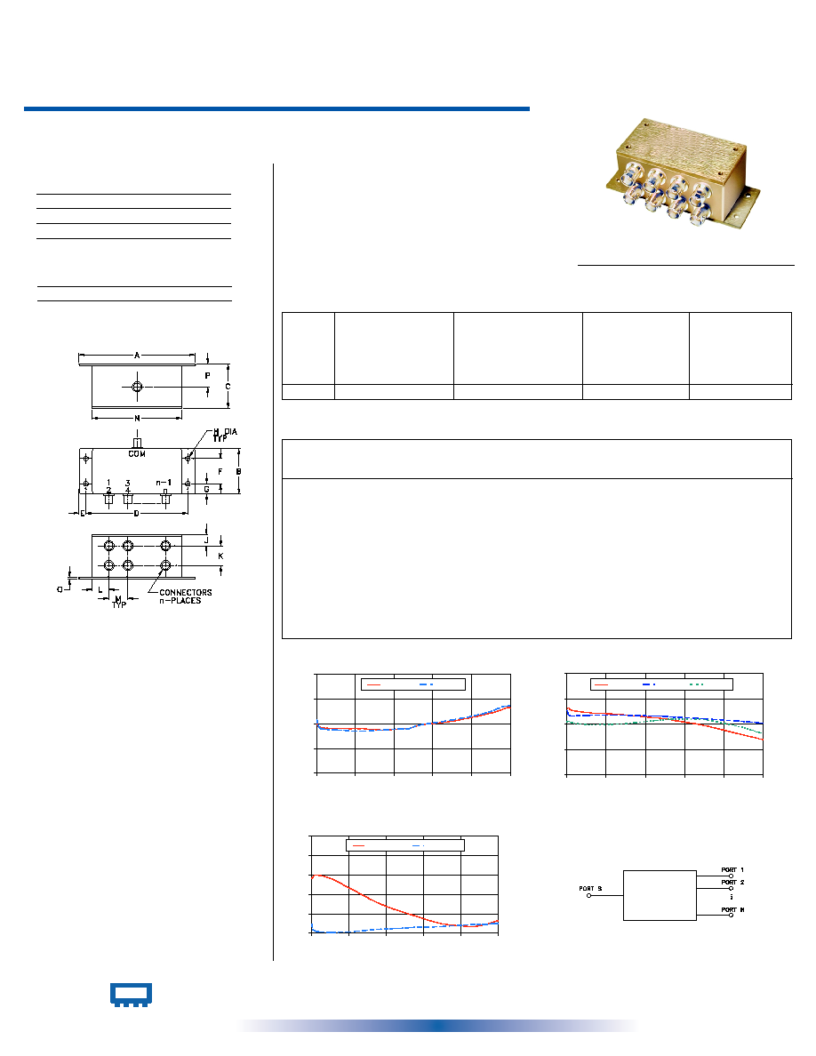
8 Way-0∞ 75
0.5 to 175 MHz
Power Splitter/Combiner
Coaxial
ZFSC-8-1-75
ZFSC-8-1-75
INSERTION LOSS
9.0
9.2
9.4
9.6
9.8
0
35
70
105
140
175
FREQUENCY (MHz)
INS
E
RT
IO
N LO
S
S
(
d
B
)
S-1(dB)
S-8(dB)
ZFSC-8-1-75
ISOLATION
22
28
34
40
46
0
35
70
105
140
175
FREQUENCY (MHz)
IS
O
L
A
T
IO
N (
d
B
)
1-2(dB)
1-7(dB)
5-7(dB)
ZFSC-8-1-75
VSWR
1.0
1.2
1.4
1.6
1.8
2.0
0
35
70
105
140
175
FREQUENCY (MHz)
VSWR
#S-VSWR
#1-VSWR
Outline Dimensions ( )
inch
mm
Maximum Ratings
Features
∑ HF/VHF
∑ radio communication
∑ federal and defense communications
∑ low insertion loss, 0.6 dB typ.
∑ good isolation, 30 dB typ.
∑ rugged, shielded case
Applications
Outline Drawing
Splitter Electrical Specifications
FREQ.
RANGE
(MHz)
PHASE
UNBALANCE
(Degrees)
ISOLATION
(dB)
INSERTION LOSS (dB)
ABOVE 9 dB
AMPLITUDE
UNBALANCE
(dB)
f
L
-f
U
0.5-175
25
20
30
20
25
20
0.5
1.0
0.6
1.1
0.7
1.3
1.0
2.5
5.0
0.2
0.3
0.5
INTERNET http://www.minicircuits.com
P.O. Box 350166, Brooklyn, New York 11235-0003 (718) 934-4500 Fax (718) 332-4661
Distribution Centers
NORTH AMERICA 800-654-7949 ∑ 417-335-5935 ∑ Fax 417-335-5945 ∑ EUROPE 44-1252-832600 ∑ Fax 44-1252-837010
Mini-Circuits
Æ
Mini-Circuits ISO 9001 & ISO 14001 Certified
REV. OR
M94964
ZFSC-8-1-75
HY/TD/CP
060209
Typical Performance Data
A
B
C
D
E
F
G
H
4.06
1.60
1.50
3.56
.24
.88
.36
.160
103.12
40.64
38.10
90.42
6.10
22.35
9.14
4.06
J
K
L
M
N
P
Q
wt.
.40
.69
.58
.66
3.13
.80
.06 grams
10.16
17.53
14.73
16.76
79.50
20.32
1.52
300
L
Typ. Min.
M
Typ. Min.
U
Typ. Min.
L
Max.
U
Max.
M
Max.
L
Typ. Max.
M
Typ. Max.
U
Typ. Max.
L
Max.
U
Max.
M
Max.
L = low range [f
L
to 10 f
L
]
M = mid range [10 f
L
to f
U
/2] U = upper range [f
U
/2 to f
U
]
Operating Temperature
-55∞C to 100∞C
Storage Temperature
-55∞C to 100∞C
Power Input (as a splitter)
1W max.
Internal Dissipation
0.62W max.
CASE STYLE: R29
Connectors
Model
Price
Qty.
BNC
ZFSC-8-1-75
$102.95
(1-9)
electrical schematic
Coaxial Connections
SUM PORT
S(COM)
PORT 1,2,3,4,5,6,7,8
1,2,3,4,5,6,7,8
0.50
9.41
9.44
9.41
9.44
9.43
9.43
0.09
37.59
37.02
34.87
34.62
0.98
1.56
1.09
1.09
1.50
9.38
9.41
9.38
9.41
9.40
9.39
0.12
37.91
36.21
35.08
34.69
0.50
1.58
1.04
1.04
4.38
9.37
9.38
9.37
9.38
9.37
9.36
0.13
37.32
35.99
34.77
34.34
0.21
1.60
1.02
1.02
19.00
9.36
9.33
9.36
9.32
9.36
9.35
0.13
36.71
36.11
34.21
33.88
0.92
1.56
1.01
1.01
40.00
9.36
9.30
9.36
9.30
9.35
9.34
0.10
36.44
36.12
34.14
33.98
1.16
1.44
1.02
1.03
61.00
9.35
9.26
9.35
9.26
9.35
9.35
0.10
35.97
36.09
34.45
34.36
0.89
1.32
1.04
1.04
77.00
9.36
9.29
9.36
9.29
9.36
9.36
0.08
35.54
35.92
34.72
34.82
0.79
1.25
1.05
1.05
83.00
9.36
9.28
9.36
9.28
9.37
9.36
0.08
35.41
35.93
34.77
34.94
0.72
1.23
1.05
1.06
94.00
9.39
9.30
9.39
9.30
9.39
9.39
0.09
34.98
35.72
34.93
35.18
0.68
1.19
1.06
1.06
122.00
9.42
9.33
9.42
9.33
9.43
9.43
0.10
33.72
35.31
34.50
35.08
0.51
1.10
1.07
1.08
150.00
9.47
9.38
9.47
9.38
9.48
9.48
0.11
31.93
34.78
32.94
33.65
0.65
1.07
1.09
1.10
163.00
9.50
9.41
9.51
9.41
9.52
9.52
0.11
31.10
34.52
31.95
32.72
0.75
1.09
1.09
1.11
169.00
9.52
9.43
9.53
9.43
9.54
9.54
0.12
30.74
34.39
31.47
32.24
0.76
1.11
1.10
1.11
172.00
9.53
9.43
9.53
9.43
9.54
9.54
0.11
30.53
34.30
31.23
32.00
0.80
1.12
1.10
1.11
175.00
9.53
9.44
9.54
9.44
9.56
9.55
0.12
30.33
34.25
31.03
31.79
0.78
1.13
1.10
1.11
Insertion Loss
(dB)
VSWR
S
VSWR
1
S-1
S-2
S-3
Isolation
(dB)
1-2
3-4
S-4
5-7
Amplitude
Unbalance
(dB)
VSWR
7
S-6
S-8
1-7
Frequency
(MHz)
Phase
Unb.
(deg.)