MITSUMI
Electronic Governer for DC Motors LAG674
Electronic Governer for DC Motors
Monolithic IC LAG674
Outline
This is an IC for DC motor electronic governors, developed with emphasis on low-voltage operation; it has
control functions operating at voltages as low as 0.9 V (with performance guaranteed to 1.0 V).
Features
1. Stabilized internal reference voltage generation circuit with a flat temperature characteristic (±100 ppm) and
excellent reduced-voltage characteristics (operation stable down to 0.9 V)
2. Low startup voltage of 0.75 V max.
3. Internal power transistor ensures large startup currents (500 mA-min at 1.0 V using the standard circuit)
4. On/off switching pin provided; on/off control possible at low startup voltages, power supply current while
off is 5µA or less
Package
SOP-8A (LAG674F)
Absolute Maximum Ratings
Item
Symbol
Ratings
Units
Operating temperature
T
OPR
-20~+60
∞
C
Storage temperature
T
STG
-40~+125
∞
C
Power supply current
V
CC
7
V
Power consumption I
Pd1
600
mW
Power consumption II
Pd2
900
*
1
mW
Operating voltage
Vop
5
V
Output current
IL
1.0
*
2
A
*
1: When mounted on a 20 30 0.5 mm printed circuit board (glass-reinforced epoxy).
*
2: When Pd exceeds the rated value, the value of Pd takes precedence.
MITSUMI
Electronic Governer for DC Motors LAG674
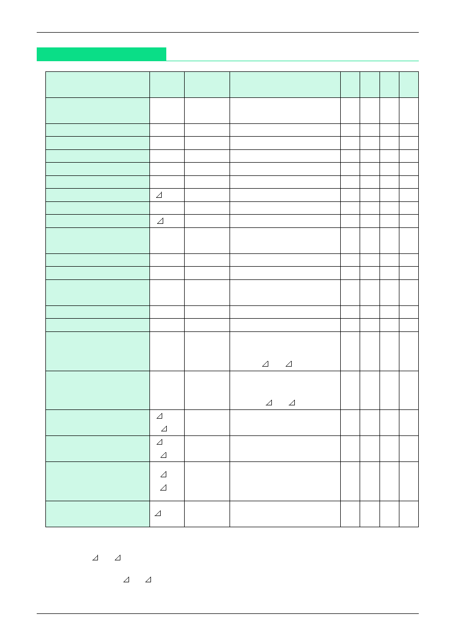
Electrical Characteristics
(Except where noted otherwise, Ta=25
∞
C)
Item
Symbol
Measurement
Measurement conditions
Min. Typ. Max. Units
circuit
Recommended operating
Vccopr
1.0
5.0
V
voltage range
Leakage current while off I
Ileak1
1
V
CC
=5V, SW OFF
20
µA
Leakage current while off II
Ileak2
1
V
CC
=1.2V, SW OFF
5
µA
Power supply current while on I
I
CC
1
2
V
CC
=5V, SW ON
1.2
1.8
mA
Power supply current while on II
I
CC
2
2
V
CC
=1.2V, SW ON
1.0
1.5
mA
Reference voltage
Vref
2
V
CC
=1.2V
115
127
140
mV
Reference voltage fluctuation
Vref
2
V
CC
=1.0~5.0V
-0.5
0.5 mV/V
Output voltage
VM
3
V
CC
=1.2, R
M
=6
0.56 0.61 0.66
V
Reference voltage fluctuation
VM
3
V
CC
=1.0~5.0V, R
M
=6
-5
5
mV/V
Pin 7 threshold
Voltage at which Icc reaches 90mA
Motor ON/OFF SW
VTH
1
RM=6
, IM=I
CC
-1mA
0.3
0.43
0.5
V
Pin 7 input current I
I IN1
1
V
IN
(7PIN) =0.5V
0.8
1.6
3.4
µA
Pin 7 input current II
I IN2
1
V
IN
(7PIN) =3V
35
50
70
µA
Starting power supply voltage
Vccs
3
Voltage at which IM reaches 30mA
RM=1.2
, IM=VM/1.2
0.75
V
Startup current
IMS
3
V
CC
=1.0V, R
M
=1.2
500
mA
Output saturation voltage
Vosat
4
V
CC
=1.0V, IM=200mA
0.2
V
V
CC
=1.0~5.0V
Bridge ratio
K
5
IM=25~200mA
6.7
7.0
7.3
K= VM/ VA
*
1
V
CC
=1.0~5.0V
Output resistance
Ro
5
IM=25~225mA
50
80
120
m
Ro= VM/ IA
*
2
Reference voltage temperature
Vref
2
V
CC
=1.2V
±100
ppm/T
characteristic
/ Ta
Ta=-20~60∞C
*
3
Output voltage
VM
3
V
CC
=1.2V, R
M
=6
±150
ppm/T
temperature characteristic
/ Ta
Ta=-20~60
∞
C
*
3
Bridge ratio temperature
K
V
CC
=1.0~5.0V
characteristic
/ Ta
5
IM=25~200mA
±100
ppm/T
Ta=-20~60∞C
*
3
Output voltage aging drift
VMT
3
V
CC
=1.2, R
M
=6
characteristic
T=15S~10M
±0.1
%
Measurement conditions: Except where noted otherwise, in measurement circuits V
CC
=1.2V
*
1: At a certain point within the range V
CC
=1.0 to 5.0 V, IM=25 to 200 mA, the value of VA is varied and
the value VM/ VA is determined.
*
2: At a certain point within the range V
CC
=1.0 to 5.0 V, the value of IM is varied between 25 mA and 225
mA, and the value VM/ IA is determined.
*
3: The temperature characteristics of the reference voltage, output voltage and bridge ratio, as well as
the drift characteristic, are all reference values and are not guaranteed.
